Magnetic disk storage apparatus

a magnetic disk and storage device technology, applied in the direction of electric controllers, instruments, ignition automatic control, etc., can solve the problems of increased heat generation, adverse influences on the operation and characteristics of the magnetic head and the magnetic storage disk, and easy generation of read/write errors

Inactive Publication Date: 2004-06-29
RENESAS ELECTRONICS CORP
View PDF3 Cites 41 Cited by
  • Summary
  • Abstract
  • Description
  • Claims
  • Application Information

AI Technical Summary

Problems solved by technology

However, when the drive current of the voice coil motor is increased, power loss required to control this motor drive current in the linear manner is increased, resulting in an increase of a heat generation amount.
This heat generation occurred during the seek operation may give adverse influences to operations and characteristics of the magnetic head and the magnetic storage disk.
As a result, for instance, there is such a problem that read / write errors may be easily produced.
However, although this pulse drive system can have a merit as to the suppression of the heat generation amount by reducing the power loss, this pulse drive system can hardly realize high control precision, as compared with that of the above-explained linear drive system.
In particular, this pulse drive system can hardly secure sufficiently high positioning precision of the magnetic head during the tracking operation in which the move amount of the magnetic head is small.
In this case, when the pulse drive operation and the linear drive operation are carried out by separately employing output amplifiers, the arrangement of the magnetic disk storage apparatus becomes complex and is manufactured in a large scale.
In particular, the switching operation between the voice coil motor and the output amplifiers becomes very complex and very cumbersome.
However, it can be recognized that the above-described hybrid drive system of the pulse / linear drive modes own the following problems.
However, when the slew rate is low, the power loss (switching loss) occurred during the switching control operation is increased, so that the merits achieved by this pulse drive system are deteriorated.
In the above-described push-pull type output amplifier, a pass-through current (penetration current) problem may occur, while this pass-through current passes through a push-sided transistor to a pull-sided transistor.
When this pass-through current is increased, useless power consumption which does not contribute the output signal is increased.
Also, when an excessively large pass-through current flows from the push-side transistor to the pull-side transistor, the output transistor may be destroyed.
In the case that a voice coil motor is driven in a linear drive mode, the switching noise produced in the vicinity of the output zero point may deteriorate both control precision and stable characteristics of tracking control operation which is carried out in the vicinity of this output zero point.
However, in such an output amplifier operable in a high slew rate, a pass-through current very easily flows.
In the worst case, these push / pull transistors and / or a power supply may be brought into break-down conditions.
Even when such a break-down condition does not occur, large transition noise which may cause EMI noise is produced.
However, there is such a contradictory aspect that when this slew rate becomes excessively high, EMI noise is increased.
On the other hand, when the slew rate is low, there is another problem that power consumption caused by switching loss is increased.
As a consequence, in such a case that the above-described idling current is supplied in order to improve the linear characteristic of the output current during the linear drive operation, the following problems may occur.
Thus, the power consumption becomes excessively larger than the expected power consumption, so that heat generations are increased.
Although the power consumption is small, the switching noise is increased.
As a result, such an optimum operation cannot be achieved, while this optimum operation is required so as to drive the voice coil motor in the high precision manner.
That is, in the magnetic disk storage apparatus, the hybrid drive system may expect such a large merit as to the power consumption and the control precision, but may cause the above-explained various contradictory problems in such a case that both the pulse drive operation and the linear drive operation are commonly carried out by employing the same output amplifier.

Method used


Image

  • Magnetic disk storage apparatus
  • Magnetic disk storage apparatus
  • Magnetic disk storage apparatus

Examples


Embodiment Construction

Referring now to drawings, various embodiments of the present invention will be described in detail.

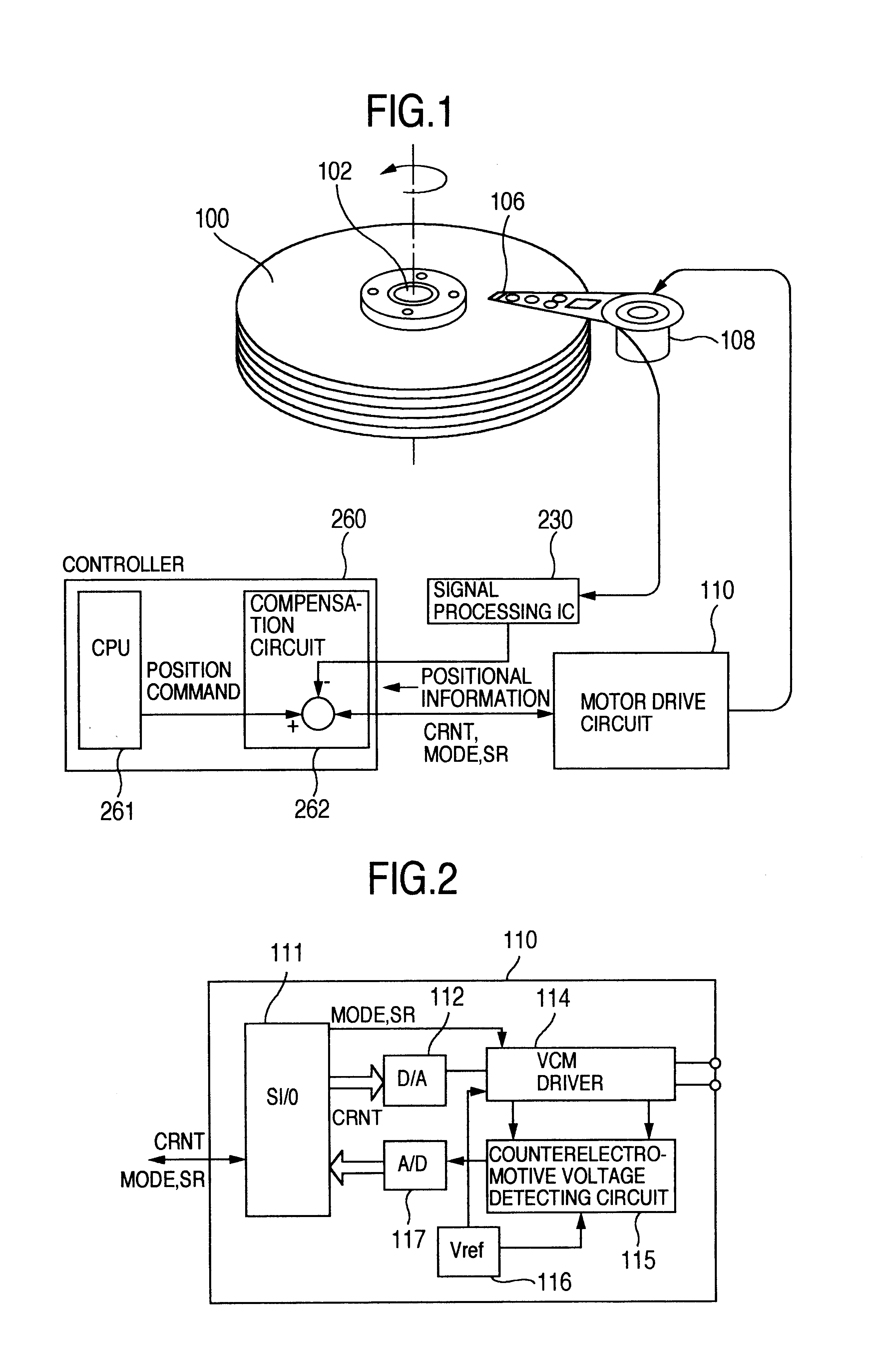
FIG. 1 conceptionally shows a magnetic disk storage apparatus to which the inventive idea of the present invention has been applied.

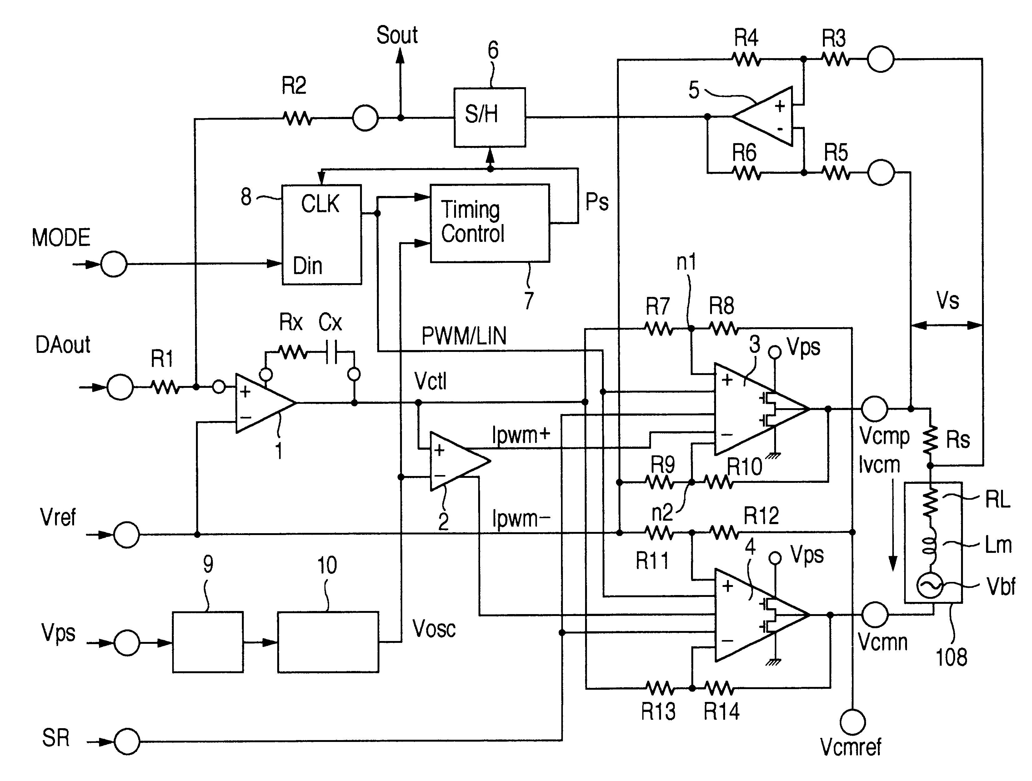
The magnetic disk storage apparatus shown in this drawing contains a magnetic storage disk 100, a spindle motor 102, a magnetic head 106, a voice coil motor 108, a motor drive circuit 110, a signal processing circuit (signal processing IC) 230, and a controller 260, and the like. The spindle motor 102 rotatably drives the magnetic storage disk 100. The magnetic head 106 reads / writes information with respect to storage tracks formed on the magnetic storage disk 100. The voice coil motor 108 moves, or transports this magnetic head 106 on the magnetic storage disk 100 along a radial direction of this disk 100. The motor drive circuit 110 drives the voice coil motor 108. The signal processing circuit: (signal processing IC) 230 reads out positional informatio...


PUM

PropertyMeasurementUnit
drive currentaaaaaaaaaa
pulse widthaaaaaaaaaa
idling currentaaaaaaaaaa

Abstract

In a magnetic disk storage apparatus, when a drive current of the voice coil motor is small, the head drive control circuit executes the linear drive mode under which the voice coil motor is driven in a linear control manner, whereas when the drive current is large, the head drive control circuit executes the pulse drive mode under which the voice coil motor is driven in a pulse width control manner. Both modes are carried out by employing a commonly-used output amplifier that is arranged as a push-pull type output circuit made of both a push-driving output transistor and a pull-driving output transistor. An operation mode of this output amplifier is set to an AB-class operation during the linear drive mode, whereas the operation mode of this output amplifier is set to a B-class operation during the pulse drive mode.

Description

1. Field of the InventionThe present invention generally relates to a control technique of a magnetic disk storage apparatus. More specifically, the present invention is directed to a control technique of a voice coil motor capable of moving a magnetic head for reading / writing information with respect to a storage track formed on a magnetic storage disk to be rotatably driven.2. Description of the Related ArtA magnetic disk storage apparatus is provided with a magnetic head, a voice coil motor, and a voice coil motor drive control circuit. The magnetic head reads / writes information with respect to storage tracks formed on a magnetic storage disk which is rotatably driven in a high speed. The voice coil motor moves this magnetic head on the magnetic storage disk in both a seek move manner and a tracking move manner. The voice coil motor drive control circuit controls a drive current of the voice coil motor, while monitoring a read condition of the magnetic head, in order to perform a...

Claims


Application Information

Patent Timeline
Patent Type & Authority Patents(United States)
IPC IPC(8): G11B21/08G11B5/55G11B15/18G11B21/10H02P25/06
CPCG11B5/5526G11B21/083G11B5/5547G11B15/18
Inventor KUROIWA, HIROSHIKOKAMI, YASUHIKO
Owner RENESAS ELECTRONICS CORP
Why Eureka
Try Eureka