Magnet powder and method for preparations thereof

a technology of magnet powder and magnetic powder, which is applied in the field of magnet powder, can solve the problems of increased cost of raw materials such as la, co, and raw materials, and achieve the effect of reducing the coercive force and improving the magnetization

Inactive Publication Date: 2004-07-06
SUMITOMO SPECIAL METAL CO LTD
View PDF4 Cites 2 Cited by
  • Summary
  • Abstract
  • Description
  • Claims
  • Application Information

AI Technical Summary

Benefits of technology

FIG. 2 is a graph showing magnetic properties of a sintered body in the case where the composition ratios y and y' are varied in conditions of x=0.2, y=y', y"=0.2, and n=5.9 in (1-x)SrO.(x / 2)La.sub.2 O.sub.3 (n-y / 2-y' / 2-y" / 2)Fe.sub.2 O.sub.3.yTiO.sub.2.y'ZnO.y"CoO. The sintered body is obtained by substituting Co and Zn for part of Fe, and by substituting La for part of Sr, and substituting Ti for part of Fe for the purpose of charge compensation in SrO.nFe.sub.2 O.sub.3 (n=5.9). As shown in FIG. 2, a phenomenon that when an amount y'(=y) for substituting Zn for Fe is increased, the lowering of the coercive force is small, and the magnetization is improved is observed.
FIG. 3 is a graph showing magnetic properties of a sintered body in the case where the composition ratio y is varied in conditions of x+y=0.25, y'=0.05, y"=0.2, and n=5.9 in (1-x)SrO.(x / 2)La.sub.2 O.sub.3 (n-y / 2-y' / 2-y" / 2)Fe.sub.2 O.sub.3.yTiO.sub.2.y'ZnO.y"CoO. The sintered body is obtained by substituting Co and Zn for part of Fe, and by substituting La for part of Sr, and substituting Ti for part of Fe for the purpose of charge compensation in SrO.nFe.sub.2 O3(n=5.9). This point is similar to the case of FIG. 2. A different point from the case of FIG. 2 is that x +y is kept at a constant value of 0.25. In this case, as shown in FIG. 3, a phenomenon that when an amount y for substituting Ti for Fe is increased, the lowering of the coercive force is small, and the magnetization exhibits a substantially constant value is observed. Ti is inexpensive as compared with La. For this reason, if the charge compensation is preformed not only by La, but also by Ti additionally, cost down can be attained.

Problems solved by technology

Moreover, raw materials such as La, Co, and the like are expensive, and there arises a problem in that, if a large amount of such raw materials is used, the raw material cost is increased.

Method used


Image

  • Magnet powder and method for preparations thereof
  • Magnet powder and method for preparations thereof
  • Magnet powder and method for preparations thereof

Examples


example 2

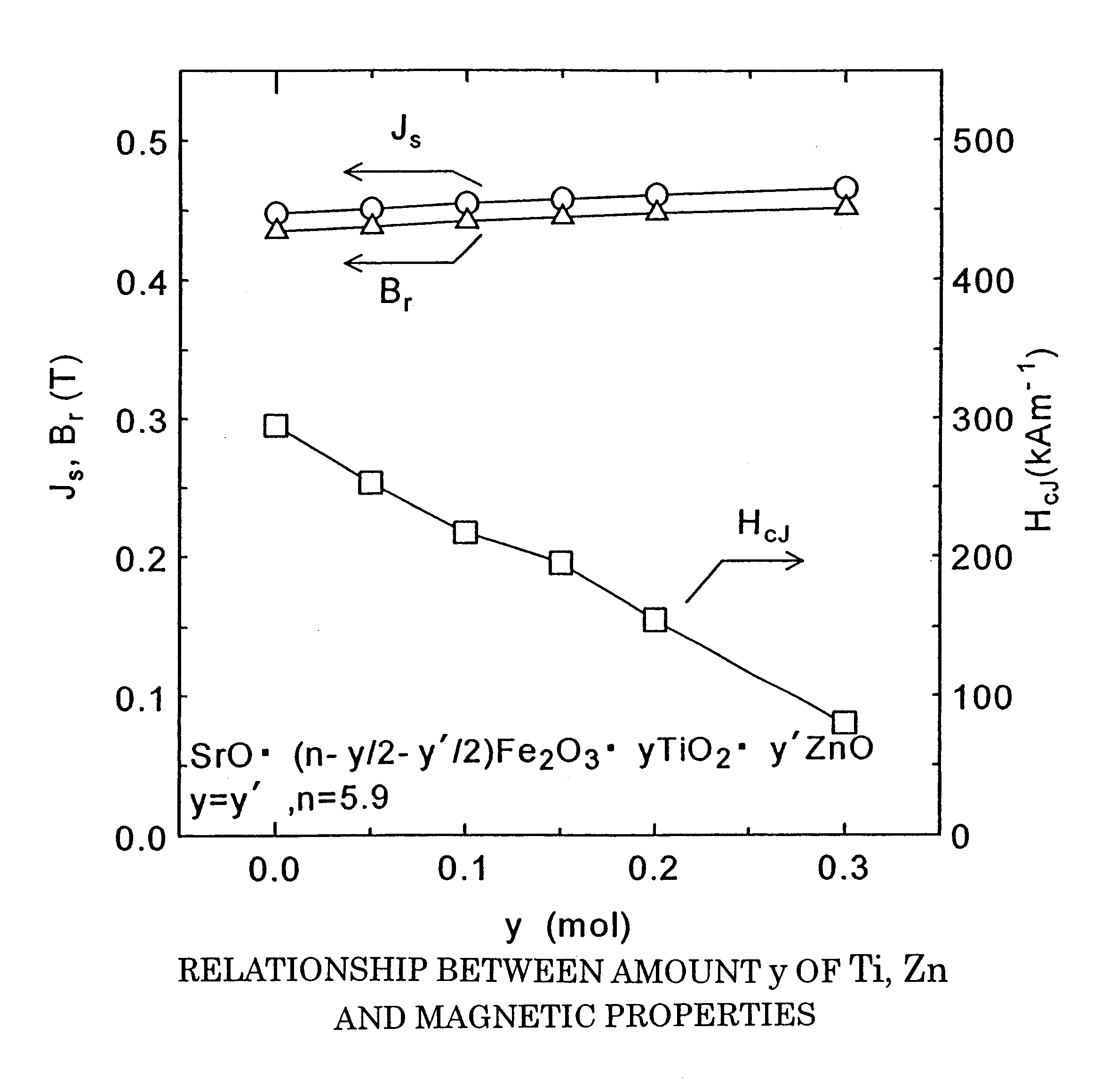
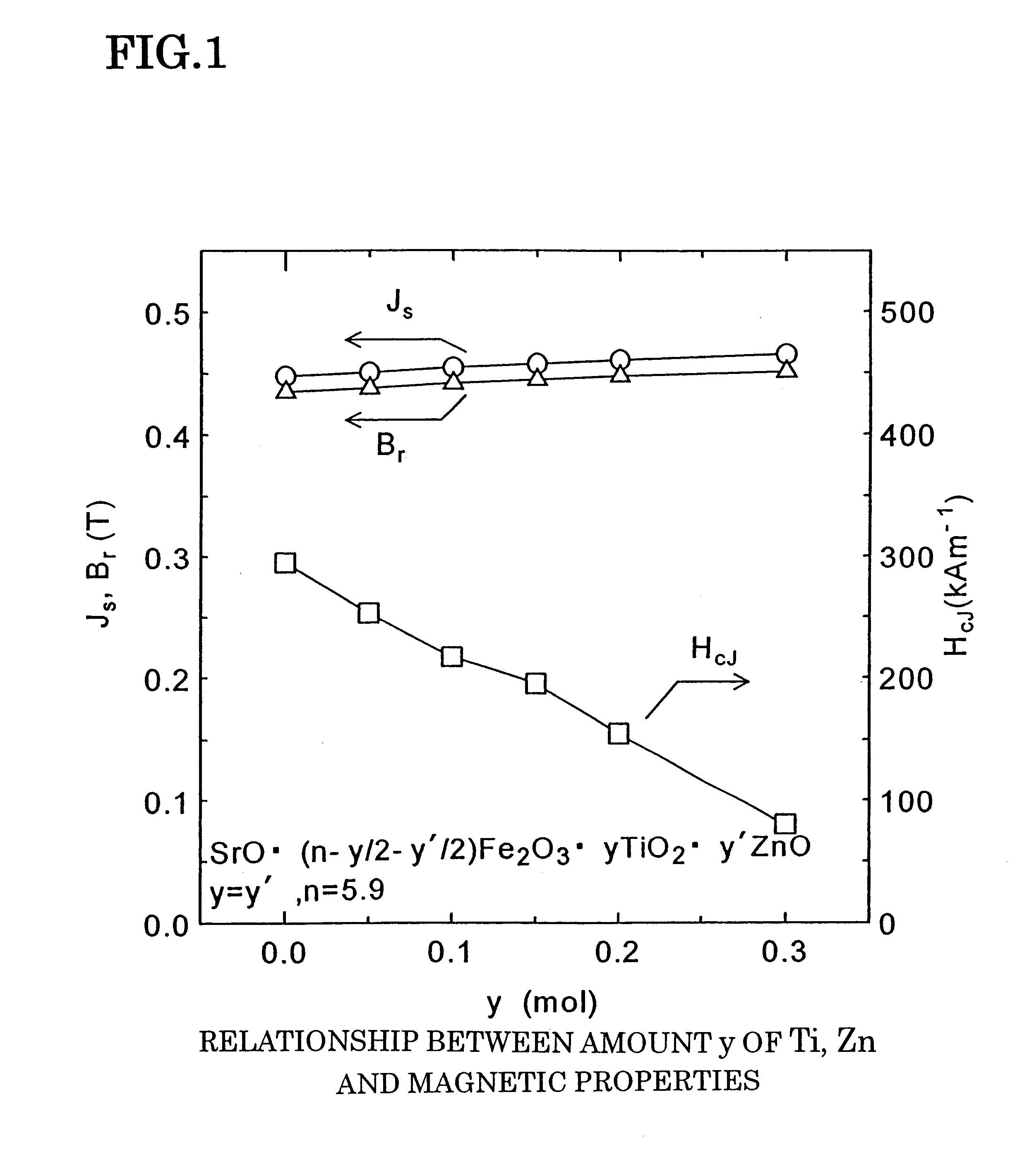
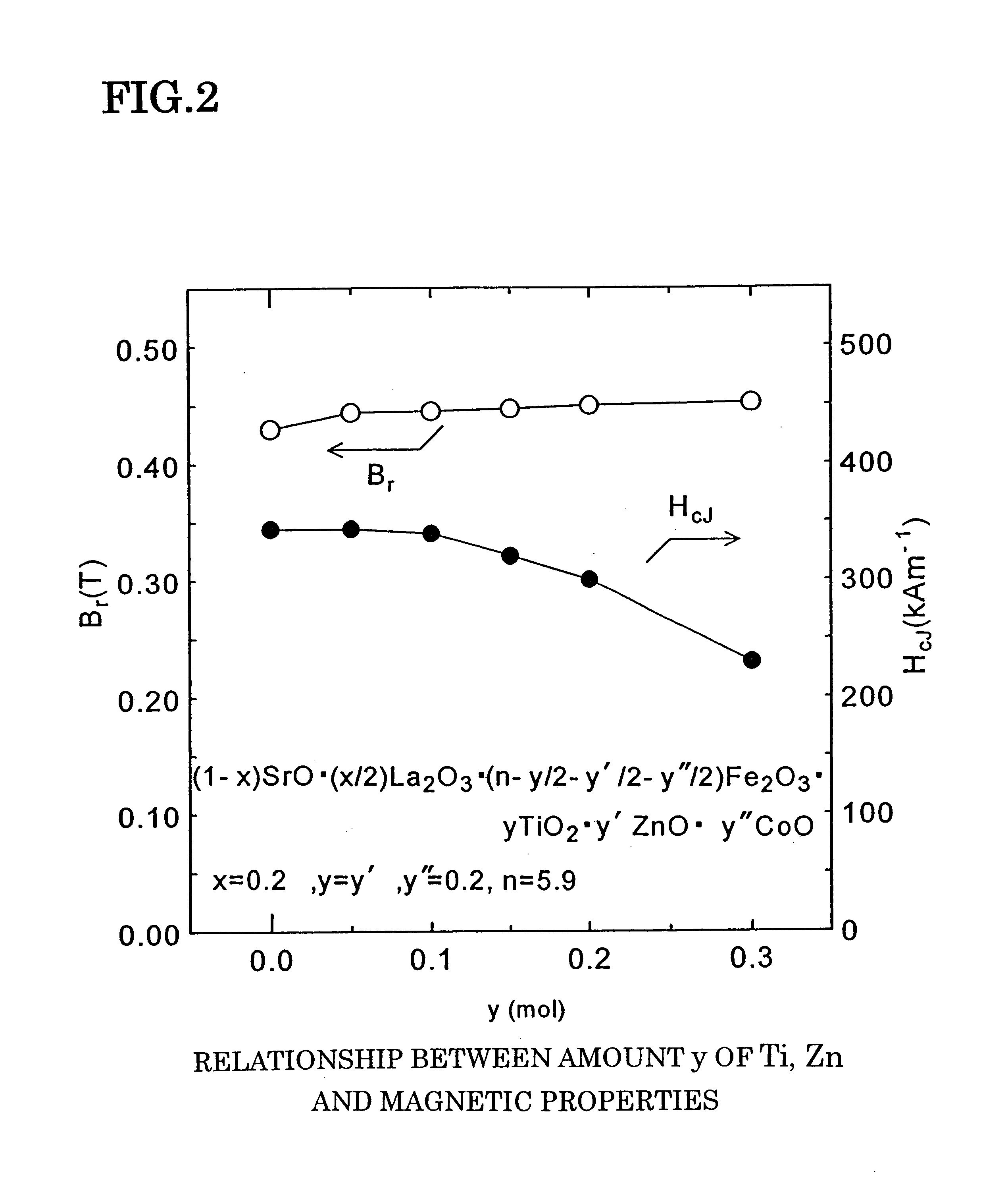
The mixing of raw materials was performed in a composition of (1-x)SrO.(x / 2)La.sub.2 O.sub.3.(n-y / 2-y' / 2-y" / 2)Fe.sub.2 O.sub.3.yTiO.sub.2.y'ZnO.y"CoO so as to satisfy the conditions of x=0.2, y=0.1, y'=0.1, and y"=0.2, and a sintered magnet was manufactured by the same operation as that of Example 1.

The temperature coefficient related to the coercive force of the obtained sintered magnet was -0.19% / .degree. C.

example 3

The mixing of raw materials was performed in a composition of (1-x)SrO.(x / 2)R.sub.2 O.sub.3.(n-y / 2y' / 2-y" / 2)Fe.sub.2 O.sub.3.yTiO.sub.2.y'ZnO.y"CoO so as to satisfy the conditions of

x=0.2,

y=0.1,

y'0.1, and

y"=0.2.

As the element R A, combinations of 0.15 of La and 0.02 of Ce, 0.15 of La and 0.05 of Pr, and 0.15 of La and 0.05 of Nd were used, and a sintered magnet was manufactured by the same operation as that of Example 1.

The magnetic properties of the obtained sintered magnet are shown in Table 1.

example 4

CaO, SiO.sub.2, Cr.sub.2 O.sub.3, and Al.sub.2 O.sub.3 were added to the magnetic powder in Example 1, so as to produce magnetic powder in the same operation as that of Example 1. A sintered magnet was manufactured by using the powder.

The magnetic properties of the obtained sintered magnet are shown in Table 2.


PUM

PropertyMeasurementUnit
temperaturesaaaaaaaaaa

Abstract

The production is performed by calcining ferrite magnetic powder in which La is substituted for part of Sr and Ti, Zn, and Co are substituted for part of Fe at temperatures of 1100° C. to 1450° C. The magnetization is improved by substituting Zn for part of Fe, and by substituting Ti for part of Fe for the purpose of charge compensation. In addition, the coercive force is improved by substituting Co for part of Fe, and by substituting La for part of Sr for the purpose of charge compensation. Ti is used for the charge compensation, so that it is possible to reduce the cost.

Description

The present invention relates to ferrite magnetic powder and a magnet using the magnetic powder, and to method for producing them.Ferrite is a generic name of a compound composed of an oxide of divalent cation metal and a trivalent iron. A ferrite magnet is used for various applications including motors, generators, and the like. As a raw material of a ferrite magnet, Sr ferrite (SrFe,.sub.12 O.sub.19) or Ba ferrite (BaFe,.sub.12 O.sub.19) having a hexagonal structure of magnetoplumbite type is widely used. These kinds of ferrite are relatively inexpensively produced by using an iron oxide and a carbonate of strontium (Sr), barium (Ba), or the like as raw materials by means of powder metallurgy.The fundamental composition of the magnetoplumbite-type ferrite is generally represented by a chemical formula of MO.6Fe.sub.2 O.sub.3. An element M is a metal of divalent cation, and is selected from a group consisting of Sr, Ba, Pb, and the like.It has been reported that, in Ba ferrite, whe...

Claims


Application Information

Patent Timeline
Patent Type & Authority Patents(United States)
IPC IPC(8): C04B35/26C01G49/00H01F1/032H01F1/113H01F1/11C04B35/40
CPCC01G49/0018C01G49/0036C01G49/0054C01G49/009C04B35/2608C04B35/2633C04B35/2641C04B35/265H01F1/113C01P2002/76C01P2006/42H01F1/10
Inventor HOSOKAWA, SEIICHITOYOTA, SACHIO
Owner SUMITOMO SPECIAL METAL CO LTD
Why Eureka
Try Eureka