
System for laser shock processing objects to produce enhanced stress distribution profiles
a technology of stress distribution and laser shock, which is applied in the field of laser shock peening systems, can solve the problems of little attention to determining useful techniques that can be provided, and achieve the effect of improving the penetration depth and better controlling the depth of residual stress
- Summary
- Abstract
- Description
- Claims
- Application Information
AI Technical Summary
Benefits of technology
Problems solved by technology
Method used
Image

Examples
first embodiment
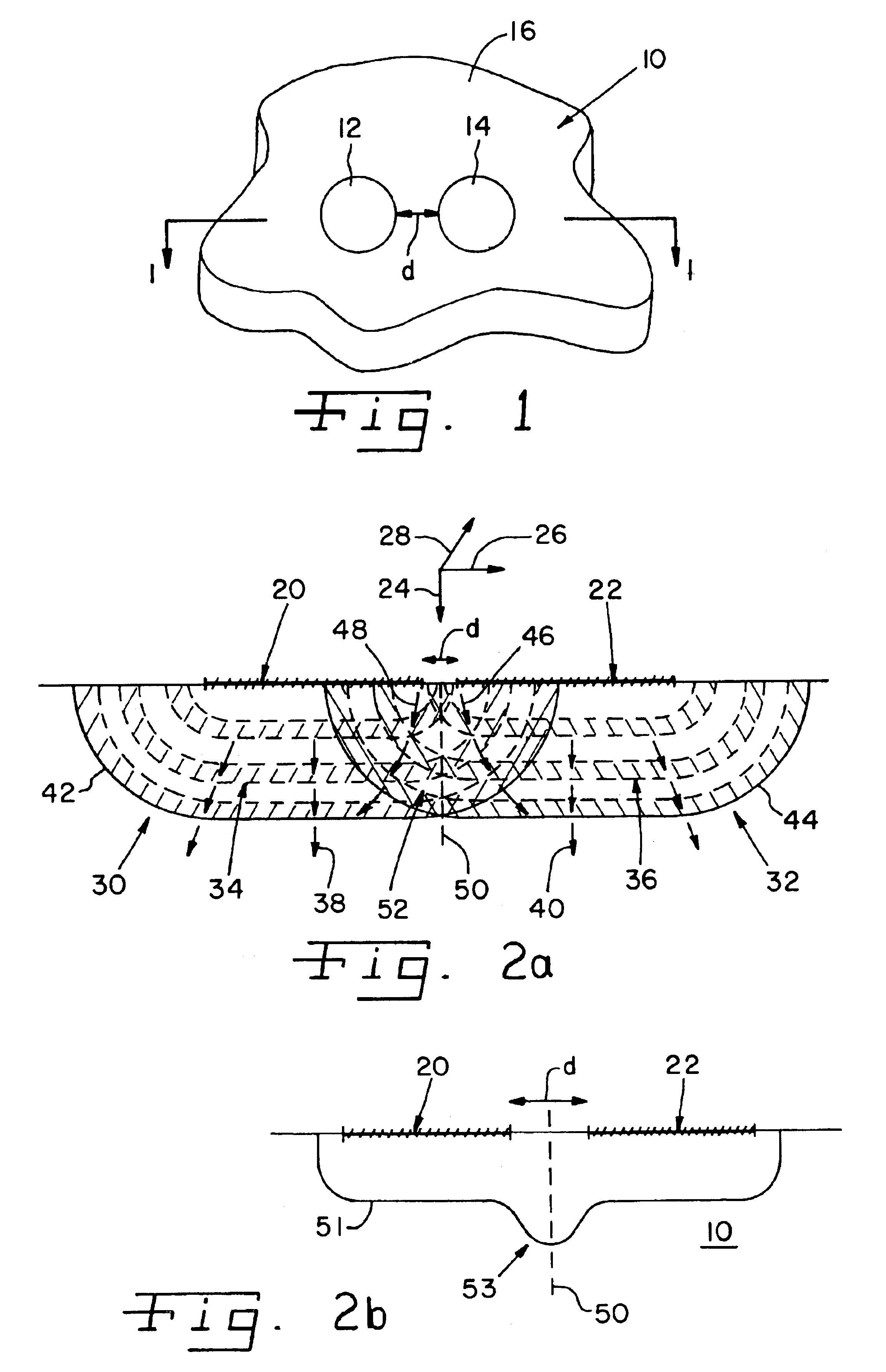
Turning now to the present invention, reference is first made to FIG. 1, which illustrates a representative laser beam spot configuration forming a set of laser shock peened surface areas on workpiece 10, according to the present invention. FIG. 2A is a cross-sectional planar view of workpiece 10 taken along lines 1--1 of FIG. 1. FIG. 2B is a similar cross-sectional planar view of workpiece 10, showing an illustrative stress contour line that is representative of the stress distribution profile which follows from the type of laser shock processing depicted in FIG. 1.
Workpiece 10 is irradiated with a set of laser beam spots 12 and 14 applied simultaneously to the surface 16 of workpiece 10 to form a respective set of adjacent non-overlapping laser shock peened surface areas coextensive with the dimensions of the laser beam spots. This treatment of workpiece 10 is conducted in accordance with a suitably configured laser shock processing operation. As shown, the laser beam spots 12, 14...
second embodiment
Reference is now made to FIGS. 8 and 9 to illustrate a laser shock processing operation, according to the present invention. As discussed further, this embodiment involves a dual-sided laser shock peening operation that forms fully opposing laser shock peened surfaces at opposing sides of a workpiece using an operating sequence that forms the relevant laser beam spots at different times.
For comparison purposes, reference is first made to FIG. 8A, which depicts the double-sided laser shock peening of a thin section using laser beams arriving at opposite sides of the workpiece at the same time. In particular, workpiece section 800 having opposite sides 802, 804 is simultaneously laser shock peened at sides 802, 804 to form laser shock peened surfaces 806 and 808, respectively.
As shown, shockwaves 810, 812 induced by laser shock peening propagate toward one another from respective laser shock peened surfaces 806, 808. Since the shockwaves 810, 812 were likewise created simultaneously, ...
third embodiment
Referring next to FIG. 10A, there is shown a cross-sectional view which depicts the double-sided, simultaneous laser shock peening of a thin section using laser beams having different pulse lengths, according to the present invention.
Illustrative workpiece 900 includes sides 902 and 904 disposed generally opposite one another and a mid-thickness plane 914. The opposing sides 902 and 904 are simultaneously laser shock peened with laser beams having different pulse lengths to form opposing laser shock peened surfaces 906 and 908, respectively. As shown, the laser shock peened surfaces 906 and 908 are respectively irradiated with representative laser beams 910 and 912, where the pulse length of laser beam 910 is longer than the pulse length of laser beam 912.
It is preferable that the laser shock peened surfaces 906, 908 be shaped and dimensioned identically. This requires, for example, the use of identically sized laser beam spots. Additionally, it is preferable that the laser shock pe...
PUM
| Property | Measurement | Unit |
|---|---|---|
| time | aaaaa | aaaaa |
| time | aaaaa | aaaaa |
| time | aaaaa | aaaaa |
Abstract
Description
Claims
Application Information