Grin-fiber lens based optical endoscopes

a technology of optical endoscopy and grin fiber, which is applied in the field of optical endoscopy and imaging systems, can solve the problems of inability to achieve image resolution in in vivo imaging systems, inability to achieve image resolution, and inability to achieve tissue damage in sensitive organs

Inactive Publication Date: 2004-07-06
LUCENT TECH INC
View PDF26 Cites 97 Cited by
  • Summary
  • Abstract
  • Description
  • Claims
  • Application Information

AI Technical Summary

Problems solved by technology

Consequently, many in vivo imaging systems do not have the image resolution obtainable in systems based on visible or IR light.
Unlike the non-invasive techniques, invasive endoscopy typically produces some tissue damage during insertion of the endoscope.
The tissue damage is particularly undesirable in sensitive organs such as the brain.
Such tissue damage has limited the use of invasive endoscopy and of optical techniques for imaging interiors of solid tissues.

Method used


Image

  • Grin-fiber lens based optical endoscopes
  • Grin-fiber lens based optical endoscopes
  • Grin-fiber lens based optical endoscopes

Examples


Embodiment Construction

1. Optical Micro-Probe and Imaging System

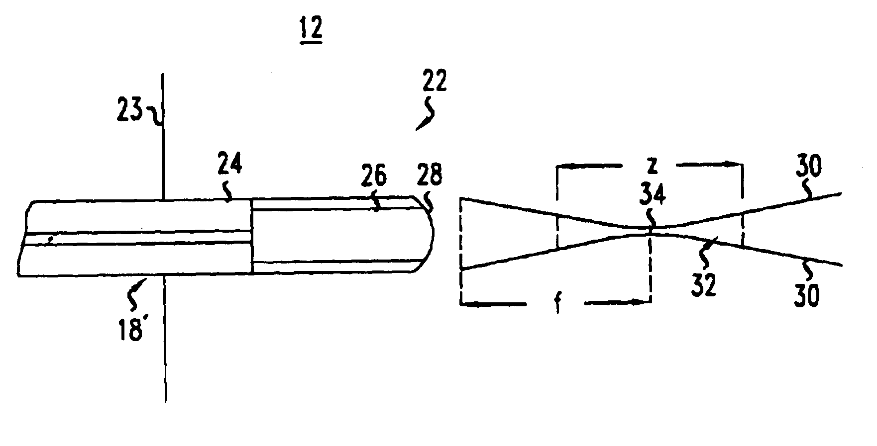
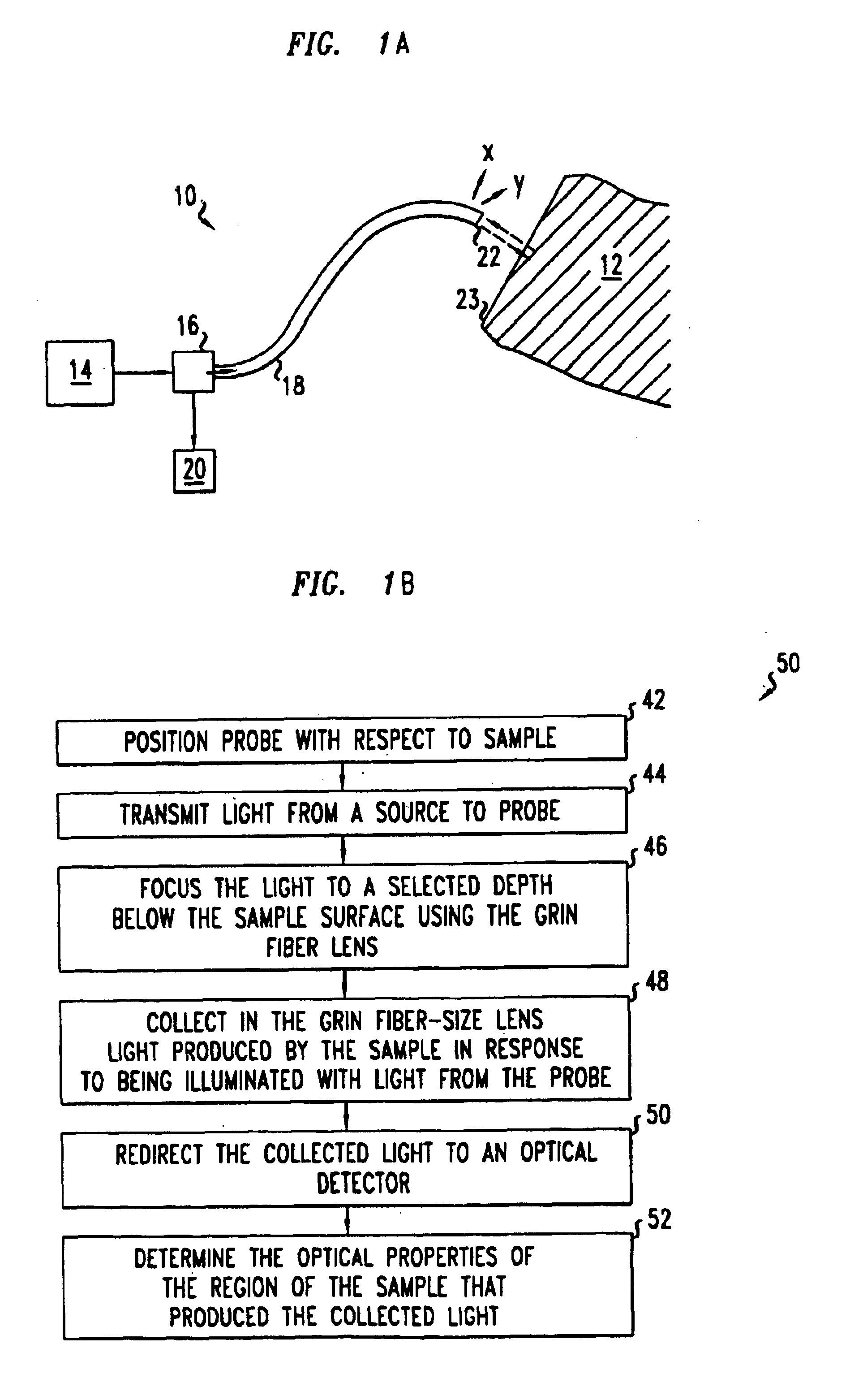
FIG. 1A shows a system 10 for optically monitoring or imaging a region of a sample 12, e.g., for endoscopic viewing of a biological tissue. Various embodiments of the system 10 determine the velocity and / or three-dimensional position of the region being monitored or imaged, e.g., via tomography. Such monitoring or imaging functions are useful for medical diagnostics and treatment, e.g., invasive imaging of anomalous tissue structures in vivo and monitoring of tissue motion during other medical procedures.

The system 10 includes a source 14 of IR, visible, or ultraviolet light, an optical splitter or circulator 16, an optical micro-probe 18, and a light detector 20. Exemplary sources 12 include monochromatic sources or multi-chromatic sources, e.g., a pulsed Ti-sapphire laser with a low coherence time of about 10.sup.-15 -10.sup.-13 seconds. The optical splitter or circulator 16 directs a portion of the light from the source 14 to the optical m...


PUM


Abstract

An optical system for monitoring or imaging a sample includes a probe, an optical splitter or circulator, and an optical detector. The probe includes an optical fiber and a GRIN fiber-size lens fused to one end of the fiber. The optical splitter or circulator receives light from a source and directs a portion of the received light to the fiber. The optical detector is coupled to receive a portion of light collected from the sample by the GRIN fiber-size lens and is configured determine a characteristic of the sample from the received light.

Description

1. Field of the InventionThis invention relates to optical endoscopes and imaging systems.2. Discussion of the Related ArtContemporary medical technology uses x-rays, sound waves, and visible light to produce in vivo images of biological tissues. Visible light and infrared (IR) imaging has better potential resolution than is obtainable with sound waves, because visible light and IR light have shorter wavelengths than sound waves. In spite of this advantage, some in vivo imaging systems use sound waves, because visible and IR light does not penetrate thick tissues. Consequently, many in vivo imaging systems do not have the image resolution obtainable in systems based on visible or IR light.One method that enables using visible and IR light in medical imaging entails the use of endoscopes that are inserted into the body being imaged. Present medical technology uses endoscopes in both non-invasive and invasive techniques. In the non-invasive techniques, the endoscope is inserted into h...

Claims


Application Information

Patent Timeline
Patent Type & Authority Patents(United States)
IPC IPC(8): A61B5/00G02B6/14G02B6/26G02B6/35G02B6/32
CPCA61B5/0048A61B5/0084G02B6/14G02B6/262A61B5/0066A61B5/0086G02B6/264G02B6/32
Inventor REED, WILLIAM ALFREDSCHNITZER, MARK J
Owner LUCENT TECH INC
Why Eureka
Try Eureka