Pipe lay system with tension compensator

a technology of tension compensator and pipe, which is applied in the direction of pipe laying and repair, mechanical equipment, transportation and packaging, etc., can solve the problems of sagging of the pipe or overload of the structural elements that guide the pipe, and achieve the effect of maintaining the pipe tension along the first trajectory substantially constan

Inactive Publication Date: 2004-07-13
SINGLE BUOY MOORINGS INC
View PDF15 Cites 20 Cited by
  • Summary
  • Abstract
  • Description
  • Claims
  • Application Information

AI Technical Summary

Benefits of technology

It is therefore an object of the present invention to provide a pipe lay system with which the tension of the pipe along the first trajectory can be maintained substantially constant. It is a further object of the present invention to provide a system in which differences in speed of the pipe section coming from the reel and the pipe section fed along the vertical trajectory can be compensated.
It is again a further object of the present invention to provide a pipe lay system having a relatively simple and reliable compensator system. Again, it is a further object of the present invention to provide a pipe lay system in which a pipe straightener is provided which is not affected by the tension compensation system and to provide a pipe straightener which can accommodate pipes of different diameter.
By displacing the tension compensator, the first pipe trajectory can be lengthened or shortened to compensate for variations in speed due to non uniform winding of the pipe and varying diameter of the spooled pipe and to compensate for sagging of the pipe due to its own weight and length variations upon unspooling in view of occurring plasticity and partial straightening of the pipe. By the movable tension compensator, the tension in the pipe along the first trajectory (the back tension) can be maintained substantially constant.
In one embodiment of the pipe lay system according to the present invention, a detector is placed near the tension compensator for measuring its position relative to an equilibrium position. A control unit receives position signals from the detector and supplies a control signal to the drive means of the reel and / or to drive means of the clamping member for changing the pipe laying speed such that the tension compensator is at least substantially returned to its equilibrium position. When the tension in the pipe section between the reel and the deflection member becomes too large, the tension compensator will move such that the first trajectory is shortened. The control unit may either increase the unwind speed of the reel, such that the tension compensator is moved back to its equilibrium position or may lower the speed at which the pipe is fed along the vertical section. Similarly, when sagging of the pipe occurs, the tension compensator is moved such that the length of the first trajectory is increased. Decreasing the unspooling speed of the reel or increasing the pipe speed along the vertical section will result in the tension compensator returning to its equilibrium position.
In one embodiment according to the present invention, a pipe straightener element is provided on the hinging arm of the tension compensator, the pipe straightener element having a curved surface and a radius of curvature substantially originating in the hinge point. In this way the point of departure of the vertical pipe section from the upper pipe straightener element to the lower two pipe straightener elements can remain constant such that the pipe straightening moments in the pipe straightener remain unaffected by movement of the tension compensator.

Problems solved by technology

Because of the varying tension along the first trajectory between the reel and the deflection member, sagging of the pipe or overload of structural elements that guide the pipe may occur.

Method used


Image

  • Pipe lay system with tension compensator
  • Pipe lay system with tension compensator
  • Pipe lay system with tension compensator

Examples


Embodiment Construction

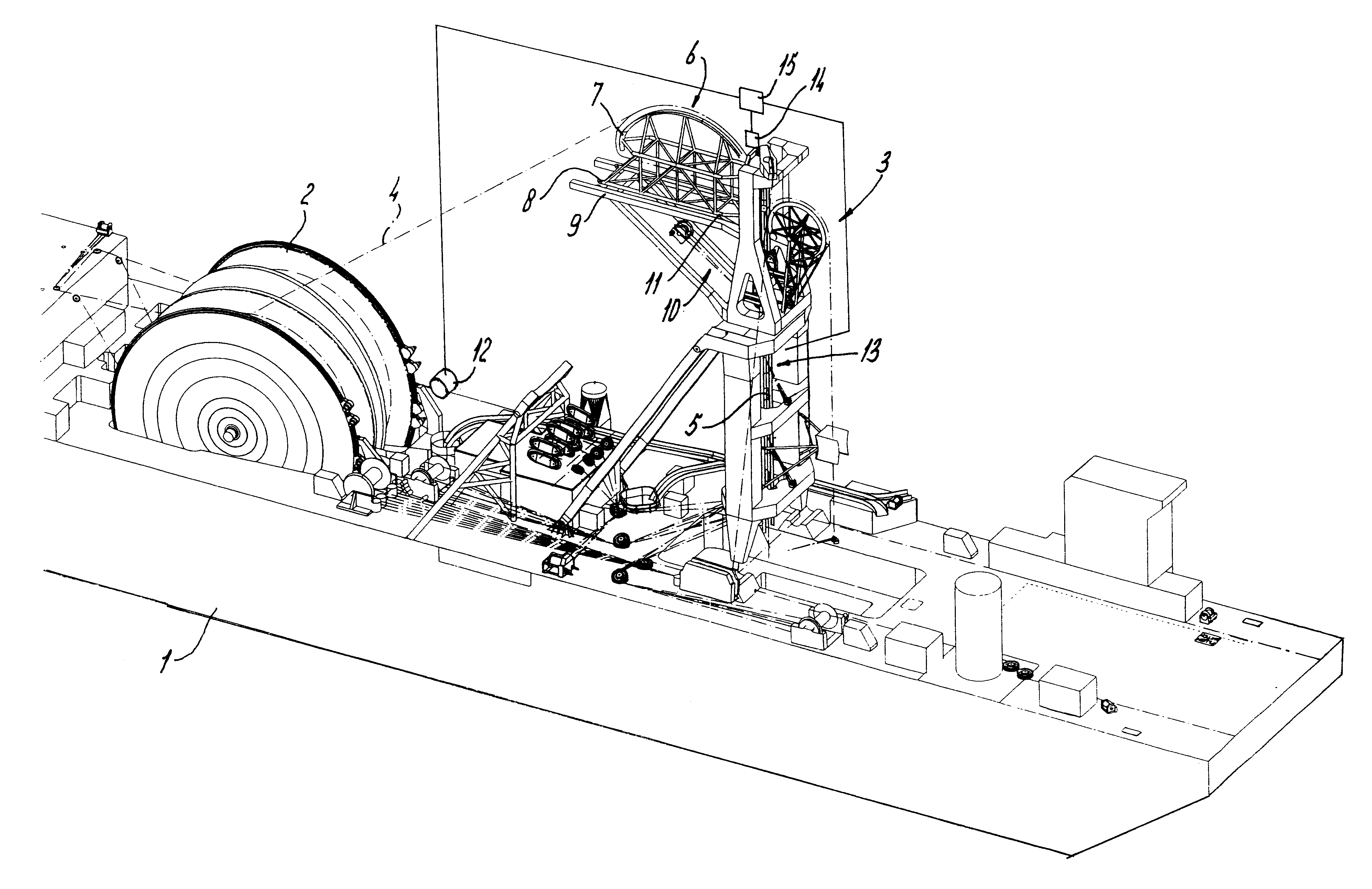
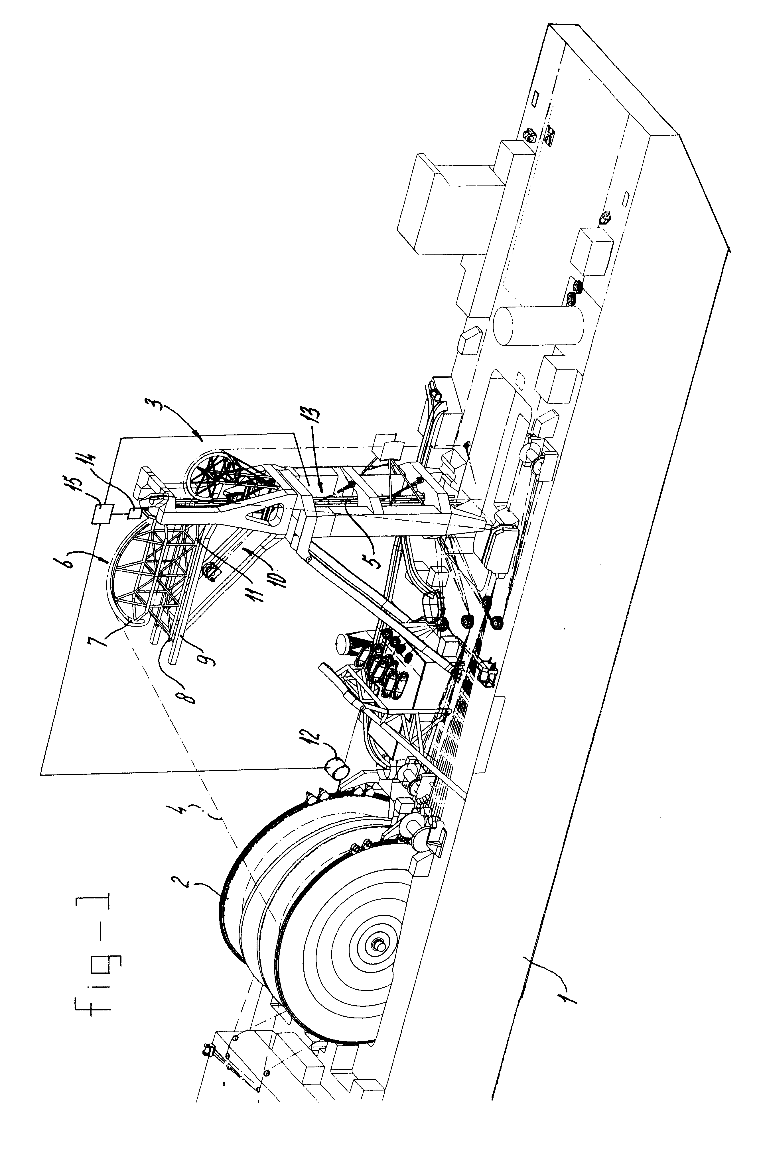
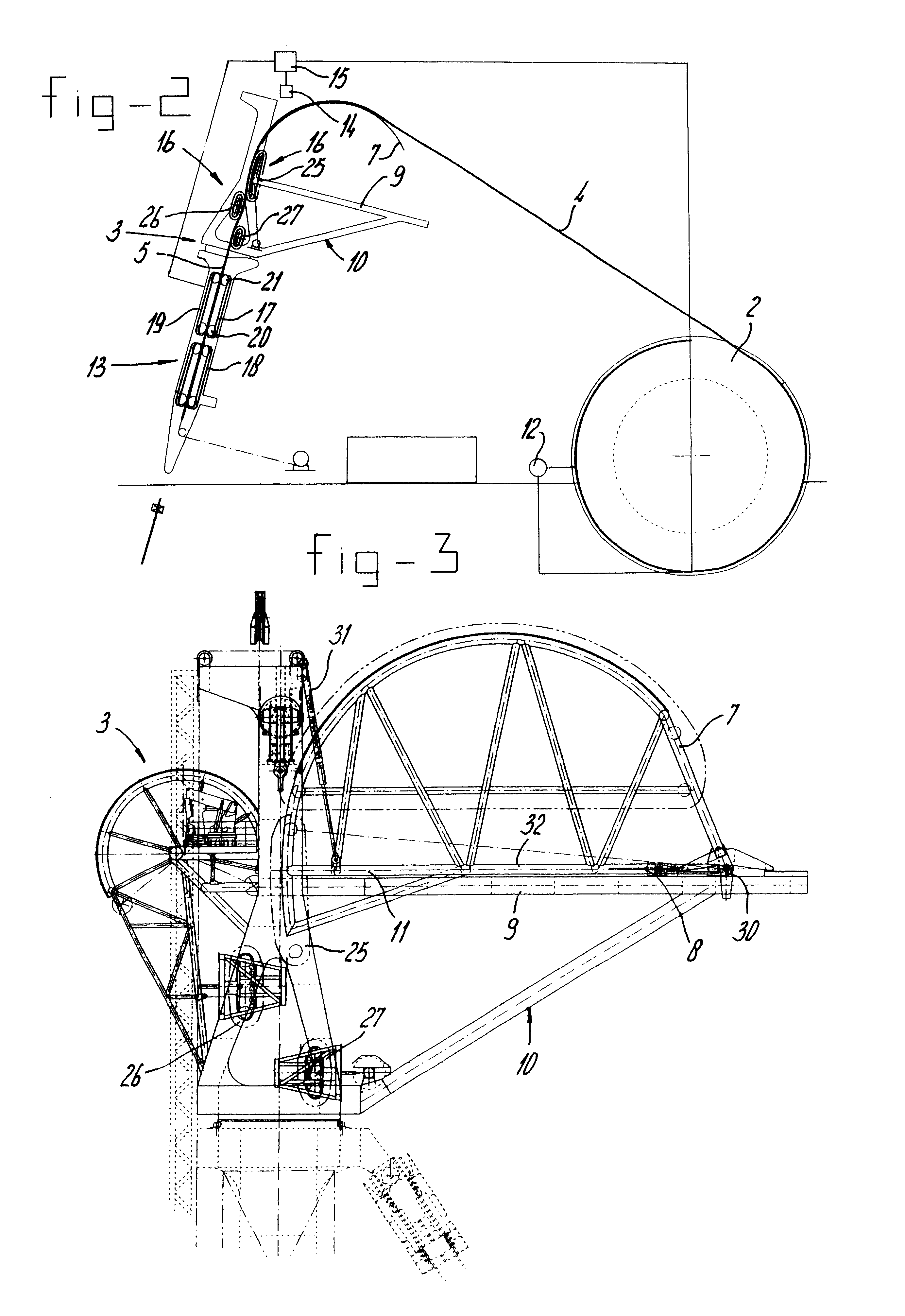
FIG. 1 shows a pipe lay vessel 1 having a reel 2 and a vertical J-lay tower 3. This vessel is especially suitable for pipe laying in deep water such as up to 2500 meters. On the reel 2, which may have a diameter of 30 meters, a steel pipe, which has been welded on shore is spooled. The pipe may have a length of 50 km and may weigh 1.500 tons. Instead of a hard pipe, a flexible pipe may also be spooled on reel 2. The pipe is fed along a first trajectory 4 to the J-lay tower 3 and passes from thereon vertically downward to the seabed along a second trajectory 5. The pipe passes over a deflection member 6 which according to the present invention comprises a tension compensator having a curved arm or pipe aligner 7 which is with a first end part 8 hingingly attached to a horizontal support arm 9 of a frame 10. The second end part 11 of the arm 7 can move relative to the J-lay tower 3 around the hinge point at the first end part 8.

The reel 2 is driven by a schematically indicated drive m...


PUM

PropertyMeasurementUnit
diametersaaaaaaaaaa
diametersaaaaaaaaaa
diameteraaaaaaaaaa

Abstract

A pipe lay vessel with a reel for carrying a length of pipe and first drive part for controlling rotation of the reel. A substantially vertical guide structure includes at its upper end a deflection member for deflecting the pipe from a first trajectory extending between the reel and the guide structure to a second, substantially vertical trajectory. A clamping member carries the vertical pipe section and has second drive for feeding the pipe along the vertical trajectory. A movable tension compensator (7) is provided at the first pipe trajectory for lengthening or shortening the first pipe trajectory to maintain a substantially constant tension of the pipe along the first trajectory during unwinding of the reel. By displacing the tension compensator, the first pipe trajectory can be lengthened or shortened to compensate for variations in speed due to non-uniform winding of the pipe and varying diameter of the spooled pipe and to compensate for sagging of the pipe due to its own weight and length variations upon unspooling in view of occuring plasticity and partial straightening of the pipe.

Description

BACKGROUND OF THE INVENTIONThe invention relates to a pipe lay vessel with a reel for carrying a length of pipe and first drive means for controlling rotation of said reel, a substantially vertical guide structure comprising at its upper end a deflection member for deflecting the pipe from a first trajectory extending between the reel and the guide structure to a second substantially vertical trajectory, and a clamping member for carrying the vertical pipe section having second drive means for feeding the pipe along the vertical trajectory.DESCRIPTION OF THE RELATED ARTSuch a vessel is known from WO-96 / 35902 in which a pipe is spooled from a storage reel to a bending shoe mounted on a derrick structure that is situated above a moon pool. The vertical pipe section is passed via a 3-point straightening assembly into the water. The known J-lay vessel is particularly suitable for pipe laying in deep water. It is known to suspend the vertical pipe section from a clamping device or tensio...

Claims


Application Information

Patent Timeline
Patent Type & Authority Patents(United States)
IPC IPC(8): F16L1/12F16L1/23
CPCF16L1/23F16L1/203B63B35/03
Inventor DE LANG, PETER ERICWOLDRING, WILHELMUS COENRADUS JOHANNES JOZEPHUSCOMMANDEUR, JOHAN ALBERT
Owner SINGLE BUOY MOORINGS INC
Why Eureka
Try Eureka