Evaporated fuel processing module

a technology of evaporation fuel and processing module, which is applied in the direction of condensed fuel collection/return, charge feed system, non-fuel substance addition to fuel, etc., can solve the problems of requiring a large amount of manpower, easy separation of connection portions, and adhesion of evaporated fuel

Inactive Publication Date: 2004-08-03
MITSUBISHI ELECTRIC CORP
View PDF13 Cites 3 Cited by
  • Summary
  • Abstract
  • Description
  • Claims
  • Application Information

AI Technical Summary

Problems solved by technology

However, in the evaporated fuel treating system in the prior art, all the parts of the canister 5 as a main part, the pressure sensor 6, the canister vent solenoid valve 7, the air filter 8 and the one-way valve 9 are connected to each other with the pipes, so that mounting the respective parts inevitably requires a work of connecting pipes and hence presents a problem of requiring a large amount of manpower.
Further, the evaporated fuel treating system in the prior art presents a problem that there are many pipe connection portions and that the connection portions are easily separated when a vehicle is broken in an accident.
Still further, the evaporated fuel treating system in the prior art presents a problem that the evaporated fuel adheres to the inside of a ru...

Method used


Image

  • Evaporated fuel processing module
  • Evaporated fuel processing module
  • Evaporated fuel processing module

Examples


embodiment 1

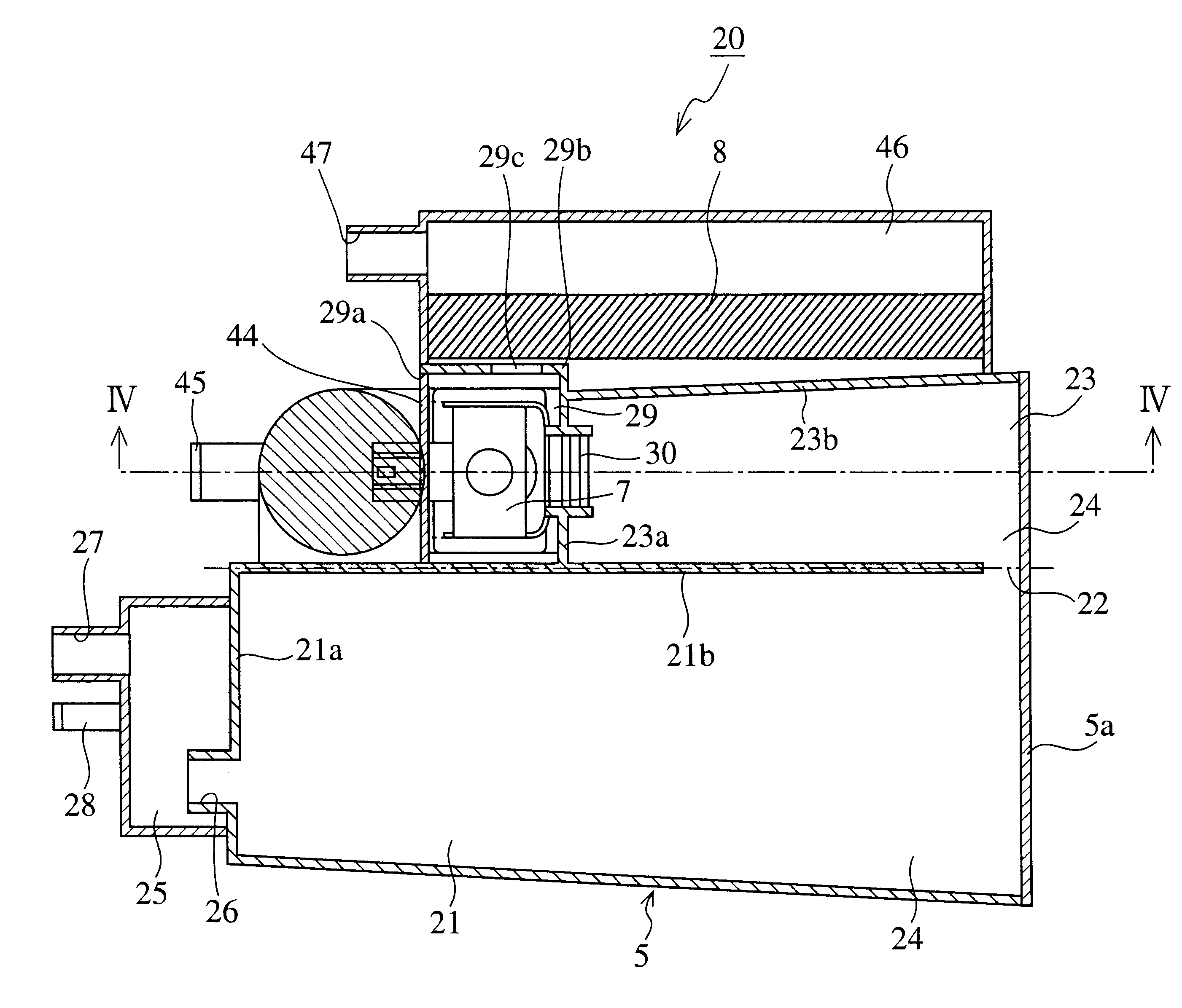
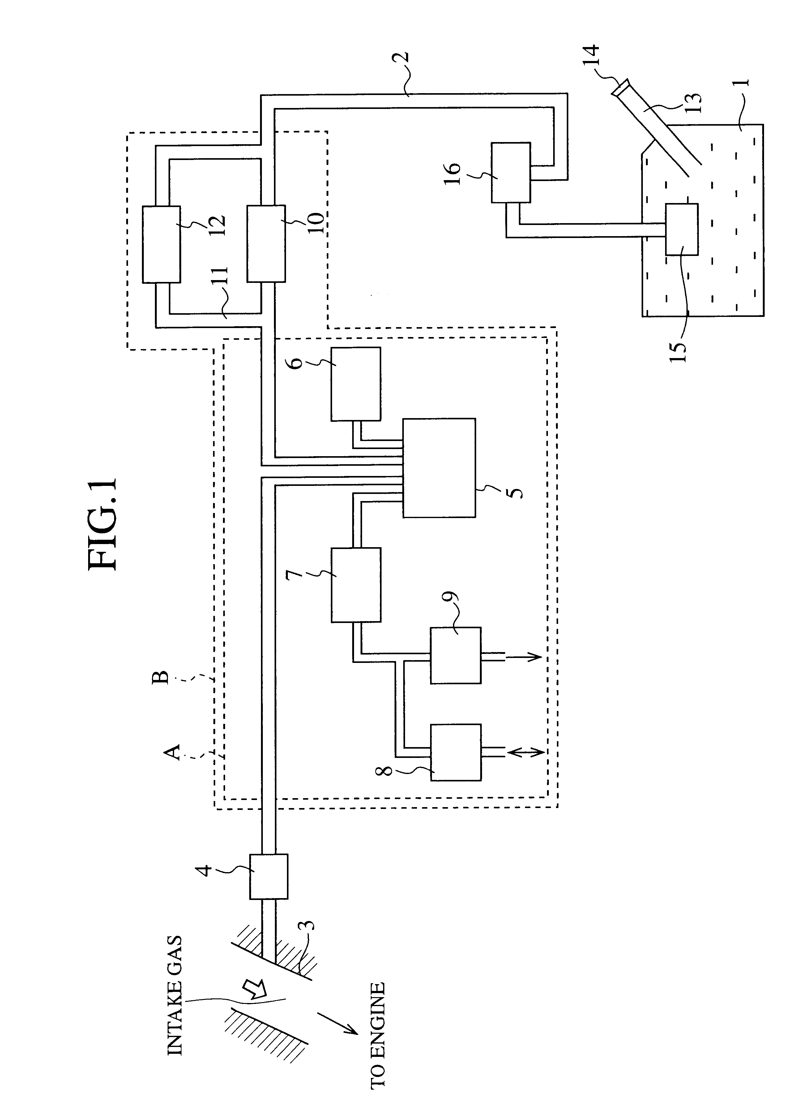
As described above, according to the present embodiment 1, the respective constituent elements surrounded by the broken like A in FIG. 1, that is, the canister 5, the pressure sensor 6, the canister vent solenoid valve 7, the air filter 8, an the one-way valve 9 are integrated into one module without connecting pipes, so that a mounting work can be finished only by mounting the module described above on the vehicle. Thus, it is possible to simplify the mounting work of the respective constituent elements on the vehicle and to fundamentally prevent the problem in the prior art, that is, to fundamentally prevent the evaporated fuel from adhering to the inside of the rubber parts for connecting the respective parts described above to the pipes and from passing little by little through the rubber parts from the inside to the atmosphere side.

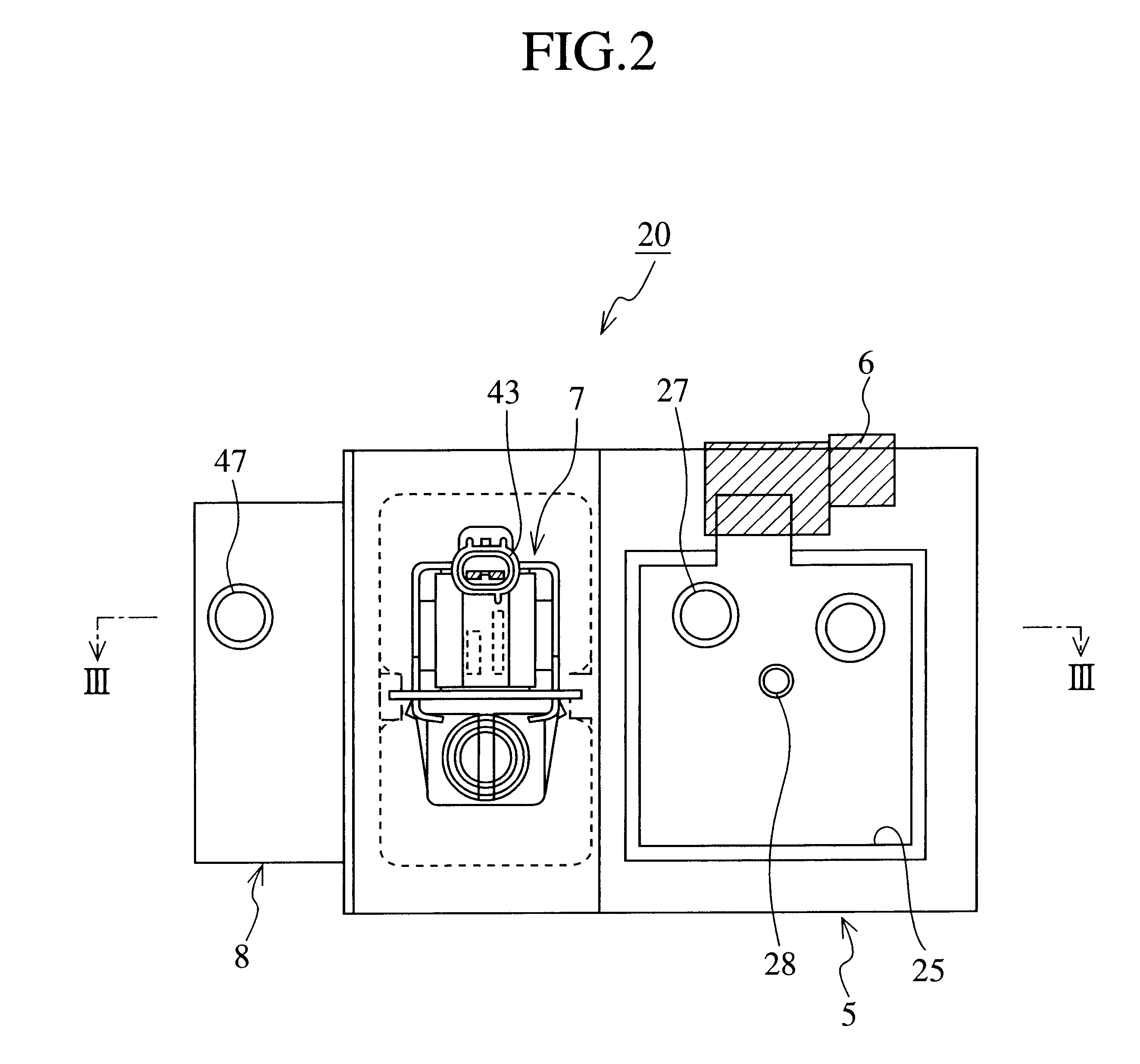
According to the present embodiment 1, the connector 43 and the cover 44 are integrally molded, so that it is possible to perform the work of mounti...

modification 3

of the Embodiment 1

In FIG. 4 is adopted the constitution that a break in the coil wire is prevented by using PPS as a material for forming the canister vent solenoid valve 7, and also in FIG. 5 is adopted the same constitution.

Since nylon is used for the casing of the canister 5 and the air filter 8 side, for example, in the case where the cover 44 is fixed to the casing of the canister 5 by a vibration welding method, different materials reduce bonding strength and sometimes can not ensure the sufficient tight sealing of the canister 5. In the case where the tight sealing of the canister 5 has precedence, it is preferable that the cover 44 is formed of nylon that is the same material as the casing of the canister 5 side.

modification 4

of the Embodiment 1

In FIG. 4, the terminal 37 of the canister vent solenoid valve 7 is directly inserted into the connector 43 integrally formed with the cover 44 and the connector 43 and the terminal 37 are connected to each other with the potting material, but to eliminate the potting work, it is also recommended that the canister vent solenoid valve 7, the connector 43, and the cover 44 be integrally molded.

In FIG. 6(a) and FIG. 6(b) is shown a unit U1 in which the canister vent solenoid valve 7, the connector 43, and the cover 44 are integrally molded. When the unit U1 is mounted on the middle chamber 29, the work of individually mounting the canister vent solenoid valve 7 and the like is not required, so that it is possible to simplify the work. Further, as shown in FIG. 6(b), by providing a pair of engaged parts 49 of the canister 5 side and a pair of engaging parts 50 engaging with the end portions of these engaged parts 49 and depending from the cover 44 of the unit U1 descr...


PUM


Abstract

An evaporated fuel treating module 20 is an integration of a canister 5, a pressure sensor 6, a canister vent solenoid valve 7, an air filter 8 and a one way-valve 9 into a unit without connecting pipes. Further, in the evaporated fuel treating module 20, also a two-way valve 10 and a bypass solenoid valve 12 may be integrated into the unit.

Description

1. Field of the InventionThe present invention relates to an evaporated fuel treating module that absorbs and treats evaporated fuel from a fuel tank and the like of a vehicle to prevent the evaporated fuel from being discharged into the atmosphere.2. Background ArtIt has been known that volume of the evaporated fuel from a fuel system such as a fuel tank, a carburetor and the like increases with rising of temperature. In particular, immediately after a vehicle stops, because the temperature in a fuel tank is being risen and an evaporation of fuel becomes active, so that it is necessary to provide an evaporated fuel treating system having a function of temporarily storing the evaporated fuel.FIG. 1 is a block diagram to show a configuration of the evaporated fuel treating system in the prior art. In FIG. 1, a reference numeral 1 denotes a fuel tank and a reference numeral 2 denotes a connection pipe for connecting an intake manifold 3 of an engine (not shown) to the fuel tank 1 via ...

Claims


Application Information

Patent Timeline
Owner MITSUBISHI ELECTRIC CORP
Why Eureka
Try Eureka