
Marking element for marking timber, especially tree trunks

a technology for marking elements and timber, applied in the field of marking elements for timber, can solve the problems of difficult to read the number, tedious and laborious manner,

Inactive Publication Date: 2004-08-10
LATSCHBACHER
View PDF16 Cites 34 Cited by
  • Summary
  • Abstract
  • Description
  • Claims
  • Application Information

AI Technical Summary

Benefits of technology

It is an object of the present invention to create a marking element of the above type whereby a recording of timber data becomes easier, faster and automatable.
The advantages of the inventive marking element lie in the fact, particularly, that a multitude of timber data and other data can be entered wirelessly into the marking element and, accordingly, read out wirelessly as well. Visual contact to the marking element is not required during the reading or writing. A plurality of marking elements, i.e., for example a plurality of tree trunks, can be wirelessly recorded at the same time. This permits, in a simple manner, the automatic and wireless recording of the data of all tree trunks carried by a truck entering a timber processing plant. Not only can a multitude of data be stored, but they can also be changed or supplemented if required, for example, with the service company and forest enterprise data, the transportation company, the logger and log mover. Dust, dirt, moisture and temperatures have no impact on the storage and read-out of the stored data. Lastly, it is also advantageous that all marking elements can initially be produced identical, i.e., for example without pre-impressed or preprinted consecutive numbers, as the data entry takes place only on site, i.e., for example in the forest. By storing the data in the marking element, i.e., on the given tree trunk itself, a read-out of the data can take place with any random wireless reading device, which does not need to be provided with any associated information.
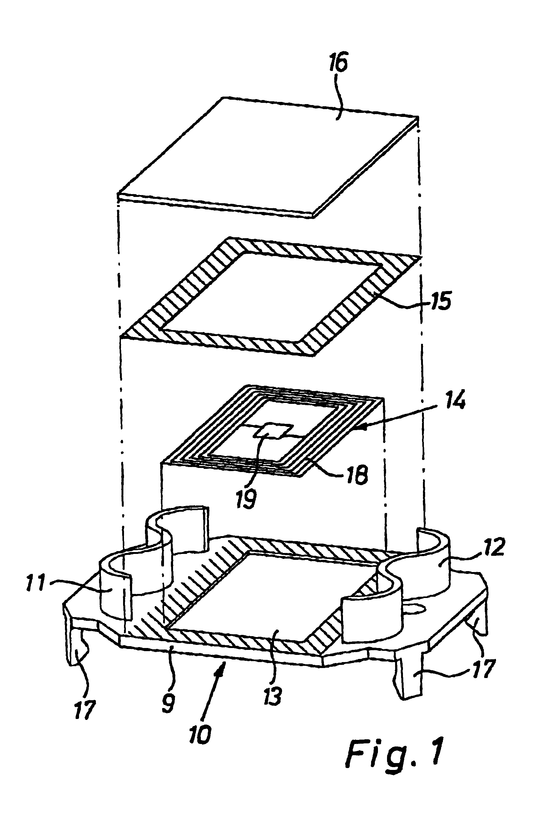
The preferably tag-shaped transponder is disposed recessed in the marking member for better mechanical protection. This is enhanced by a cover plate and / or cover film that covers the transponder, especially in a waterproof manner. This also ensures that the transponder will not be damaged when it is driven into a piece of wood, e.g., a log, and still has the required seal against water and other effects of the environment after having been driven in.
The cover plate or film, in the simplest case, is glued to the marking member, especially by means of a self-adhesive contact layer or a self-adhesive film frame encompassing the transponder. Alternately, the cover plate, which is preferably recessed in the marking member may also be welded to the marking element along its edges, preferably by means of ultrasonic welding, laser welding or hot pressing. The latter methods ensure a greater sturdiness and better protection against mechanical damage, especially while the marking element is being driven into the wood.
To facilitate the welding process and attain a better weld joint, the cover plate and / or marking element has a welding strip that encompasses the transponder to weld them to one another.

Problems solved by technology

Due to weather and location conditions, being able to read the number is often difficult.
When a larger number of tree trunks are being recorded, each individual code number must be read and entered into the computer in a tedious and labor-intensive manner to obtain an overview of the entire stock, for example when a delivery is received.

Method used


Image

  • Marking element for marking timber, especially tree trunks
  • Marking element for marking timber, especially tree trunks
  • Marking element for marking timber, especially tree trunks

Examples


first embodiment

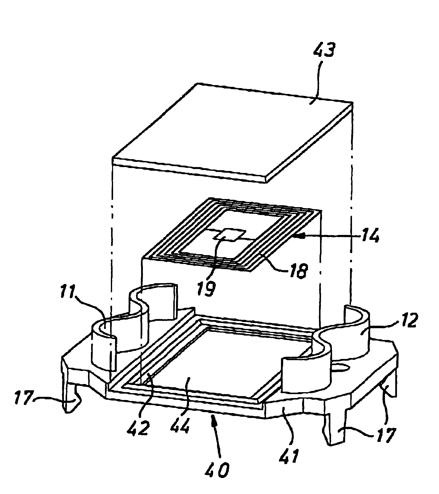
The marking element shown in FIG. 1 as a first embodiment, which is designed as a marking tag 10, has a similar design as the marking tag described in the above mentioned prior art. A tag-shaped marking member 9 has on its reverse two integral, corrugated-fastener-type drive-in projections, 11, 12 as fastening elements, which are disposed on both sides of a central, rectangular recess 13. This recess 13 serves to receive a transponder 14 that is designed as a flat film or flat tag, and the shape of which corresponds to that of the recess 13. A double-sided self-adhesive film frame 15 has a central through-opening, the shape of which corresponds to that of the recess 13 or transponder 14, respectively. A square or rectangular cover plate 16 corresponds in its outer contour to that of the film frame 15.

To secure the transponder 14, it is inserted into the recess 13 of the marking member 9, then the film frame 15 is placed around the recess 13 onto the marking element 9, and lastly the...

second embodiment

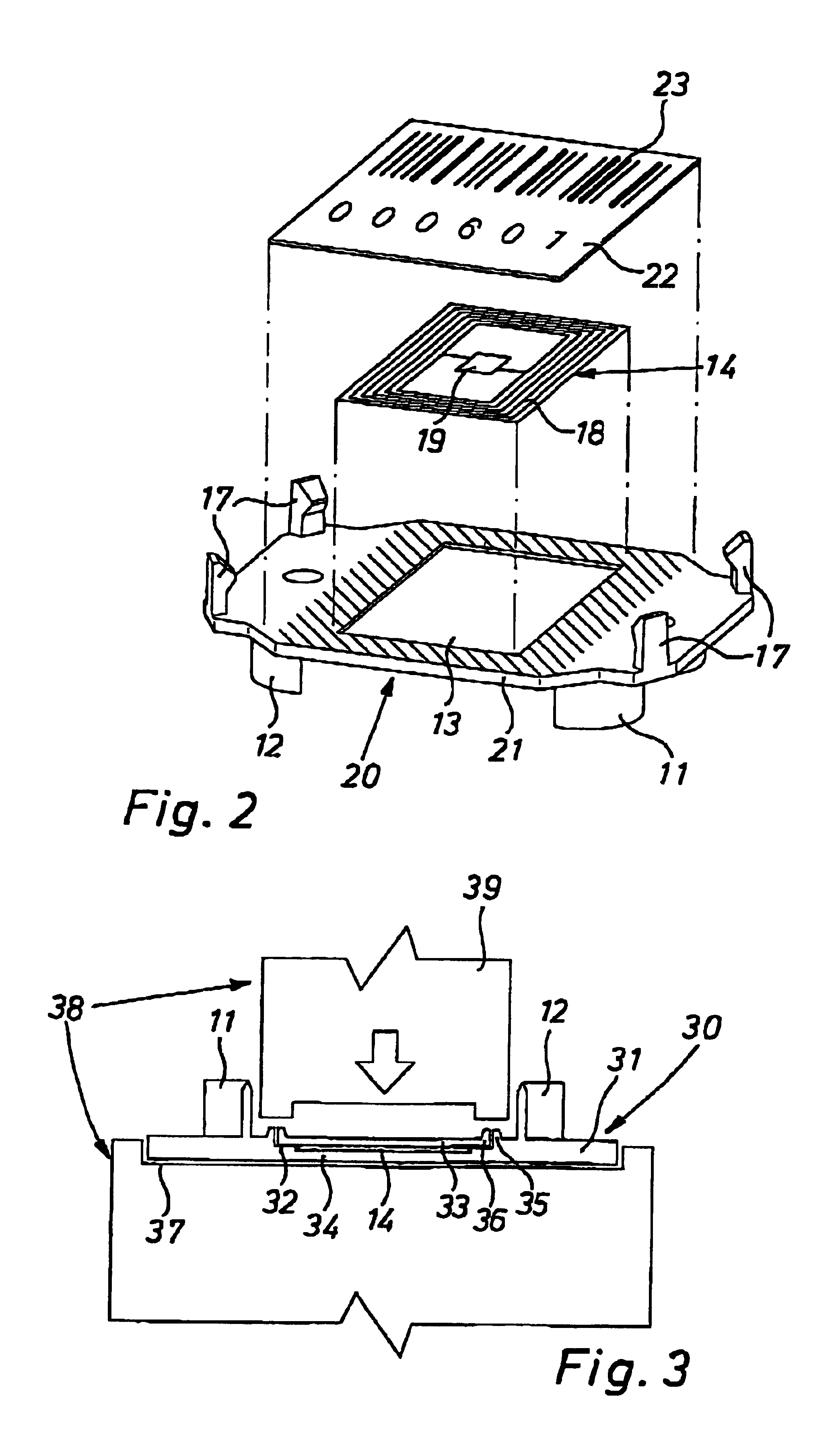
The second embodiment shown in FIG. 2 largely corresponds to the first embodiment, so that components or areas that are identical or have identical effects were given the same reference numerals and will not be described again. In this marking tag 20 the recess 13 is provided on the front of the marking member 21. The weather-resistant and waterproof cover of the transponder 14 that is inserted into the recess 13 is effected in this case by means of a cover film 22 that extends over the transponder 14. It is glued to the marking member 21 as a one-sided self-adhesive film. The rectangular cover film 22 is provided with a bar coding 23. This is optional and may also be eliminated or substituted with another coding, such as a number. This provides the option to be able to read data also in another manner, in addition to the data stored electronically.

In the first and second embodiment the transponders 14 may also be affixed on the opposite side of the marking element. In lieu of the c...

third embodiment

In the third embodiment shown in FIGS. 3 and 4, the marking member 31 of a marking tag 30 has on its reverse a first recess 32 to receive a cover plate 33, as well as a second recess 34 in the first recess 32 to receive the transponder 14. An integral welding strip 35 on the marking member 31 extends along the edge of the first recess 32. A corresponding welding strip 36 is provided integrally on the circumference edge of the cover plate 33. After inserting the transponder 14 and cover plate 33, the welding strips 35, 36 thus extend parallel and immediately adjacent to one another, as can be seen particularly in FIG. 3.

In the third embodiment, the cover plate 33 is connected to the marking member 31 by means of hot pressing. For this purpose the appropriately prepared marking tag 30 is inserted into an matching recess 37 of a fusion welding unit 38. An appropriately heated welding bar 39 that is moved in from above connects the two welding strips 35, 36 in a weather-resistant manner...


PUM


Abstract

A marking element is proposed for marking timber, especially tree trunks, having a tag-like marking element (9) with at least one fastening element (11, 12) disposed on it for fastening the marking element (10) to the timber to be marked. To provide the marking, the marking element furthermore has a transponder (14) incorporating a data storage for the wireless transmission of data. This permits the wireless storing and reading of a multitude of data without requiring visual contact.

Description

1. Technical Field of the InventionThe present invention is concerned with a marking element for marking timber, especially tree trunks, with a tag-like marking element bearing a marking, having at least one fastening element for fastening the marking element on the timber to be marked.2. Prior ArtA marking element or marking tag of this type, which is known, for example, from GB 2075464 A, carries a marking in the form of a number or other optical code, in order to mark, for example, tree trunks in the forest. The code number is then assigned, for example in a portable computer, to the corresponding timber data of the given tree trunk.A shortcoming of the known marking is that it requires a perfect line of sight to read the code number, and tables or a computer must be available to be able to derive the corresponding timber data from the number. Due to weather and location conditions, being able to read the number is often difficult. When a larger number of tree trunks are being re...

Claims


Application Information

Patent Timeline
Patent Type & Authority Patents(United States)
IPC IPC(8): A01G23/099A01G23/00G09F3/04G09F3/12G09F3/08
CPCA01G23/099G06K19/07758G09F3/04G09F3/12
Inventor LATSCHBACHER, KLAUSHUBER, JOHANNPLOIER, GERHARD
Owner LATSCHBACHER
Learn More