Position location method and apparatus for a mobile telecommunications system

Inactive Publication Date: 2004-08-17
APPLE INC
View PDF3 Cites 56 Cited by
  • Summary
  • Abstract
  • Description
  • Claims
  • Application Information

AI Technical Summary

Benefits of technology

In its second aspect, the invention may thus provide a technique for injecting calibration signals into the receiver circuit near the antenna (preferably as near to the antenna as possible), to calibrate the phase-sensitive direction-finding circuitry. It may also provide a technique for transmitting calibration signals from a near-field probe for reception by the direction finding antenna and processing by the receiver circuitry. This advantageously permits calibration of aspects of the antenna as well as the receiver circuit. The second aspect of the invention may further provide two types of beacon. A first type preferably emulates a mobile station but is fixed in position at a known location. A base station can therefore set up a call to the beacon, termed an autonomous beacon mobile, and allow the direction finding antenna and receiver circuitry at the base station to estimate the location of the beacon during the call. Comparison of the estimated and known locations, in terms of bearing and / or range, may then advantageously allow calibration of substantially all aspects of the performance of the antenna and the receiver circuitry. The second type of beacon is mounted at a cell site of a cellular telecommunications system and advantageously transmits a calibration signal for reception by any direction finding antenna situated at a neighbouring cellsite which has a footprint covering the beacon. The beacon may advantageously transmit a signal allowing calibration of bearing estimation functions of the direction finding antennas at neighbouring cell sites. In a CDMA system, for example, such a signal may be transmitted in a guard band of the transmission bandwidth. If the beacon signal is of narrow bandwidth, it may only be effective for bearing estimation. However, if a beacon signal of sufficient bandwidth can be transmitted in an available guard band, it may be used for range calibration and / or to calibrate receiver functions such as receiver filters. Calibration resolution based on a beacon signal of limited bandwidth may advantageously be improved by averaging over time.
Further advantageously, preferred embodiments of the invention may enable a direction and range estimation system which meets the FCC E911 mandate in as many environments as possible. To achieve the necessary bearing accuracy in rural cells, which may be of large radius, the invention advantageously provides in a further aspect a direction finding antenna comprising two widely-spaced, multi-element subantennas. The resolution of the individual subantennas is advantageously sufficient to remove bearing ambiguities arising from the wide spacing of the subantennas.

Problems solved by technology

These errors may arise as a bearing bias due to frequency shift, or offset, or due to Doppler frequency spread caused by the combination of mobile station motion and multipath, if signals received at the antenna elements are not sampled simultaneously.

Method used


Image

  • Position location method and apparatus for a mobile telecommunications system
  • Position location method and apparatus for a mobile telecommunications system
  • Position location method and apparatus for a mobile telecommunications system

Examples


Embodiment Construction

Specific embodiments of the invention will now be described by way of example with reference to the drawings, in which;

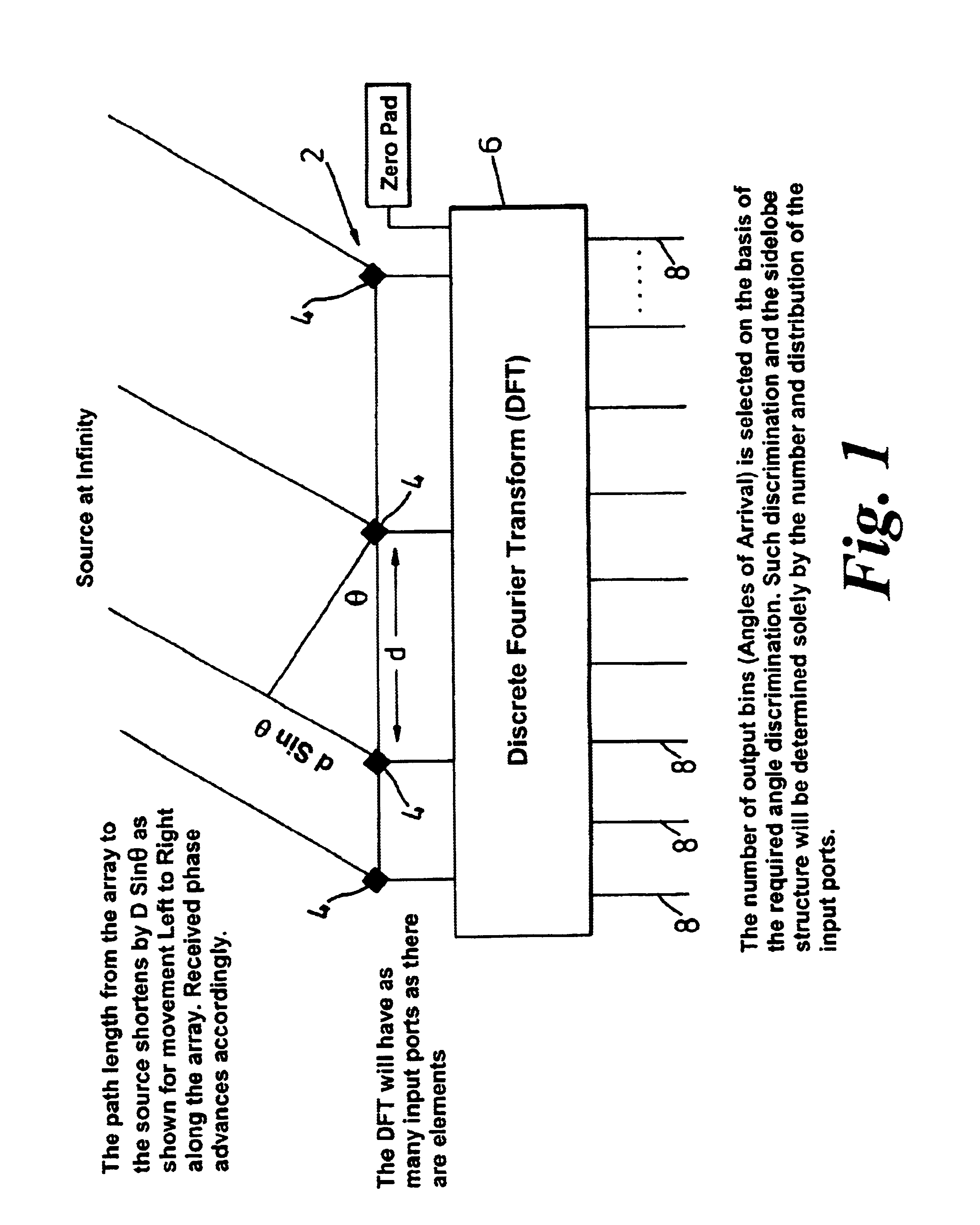
FIG. 1 illustrates the basic geometry of bearing estimation using a multi-element antenna array;

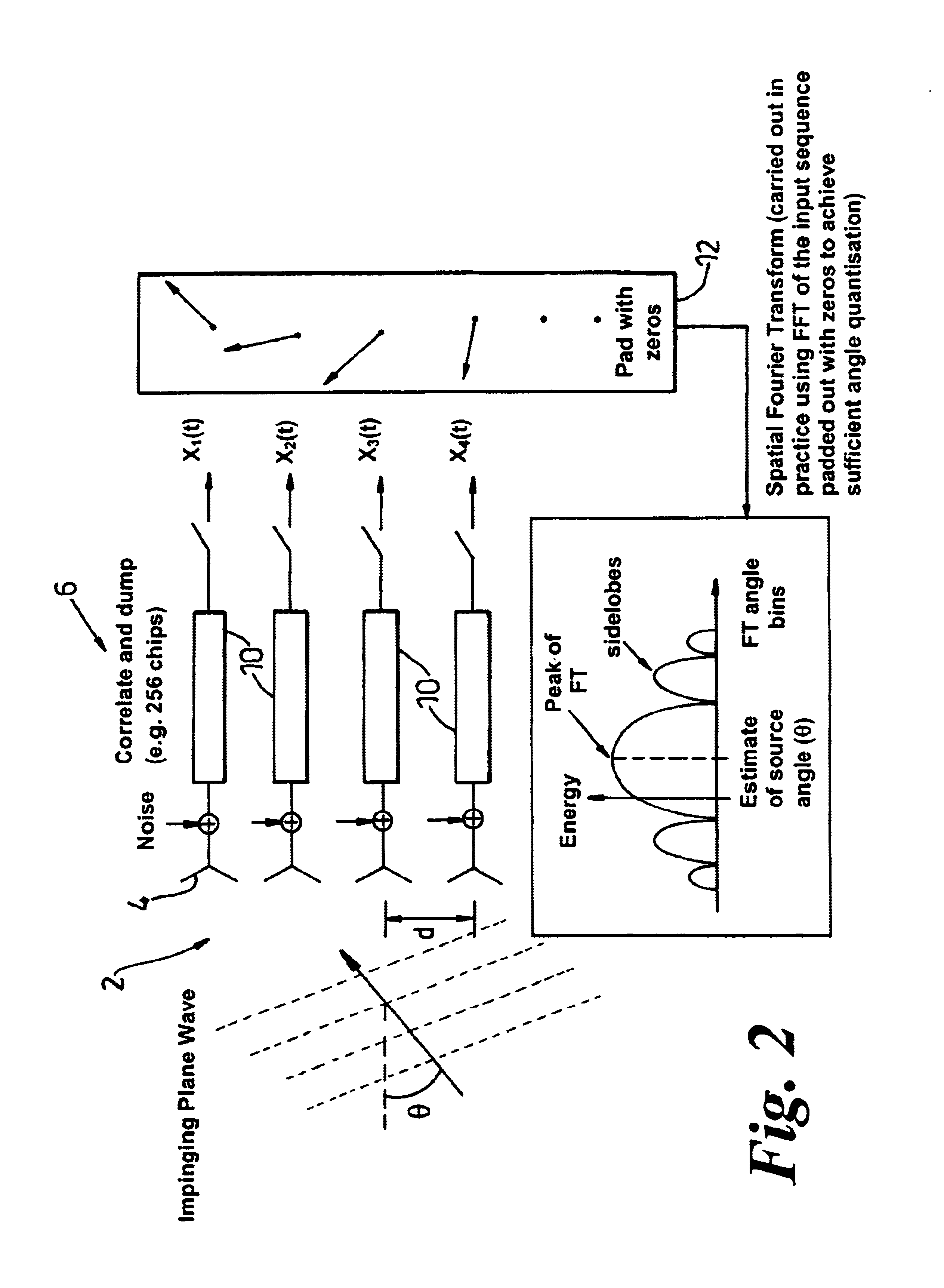
FIG. 2 illustrates the principles of the direction-finding method of a first embodiment of the invention;

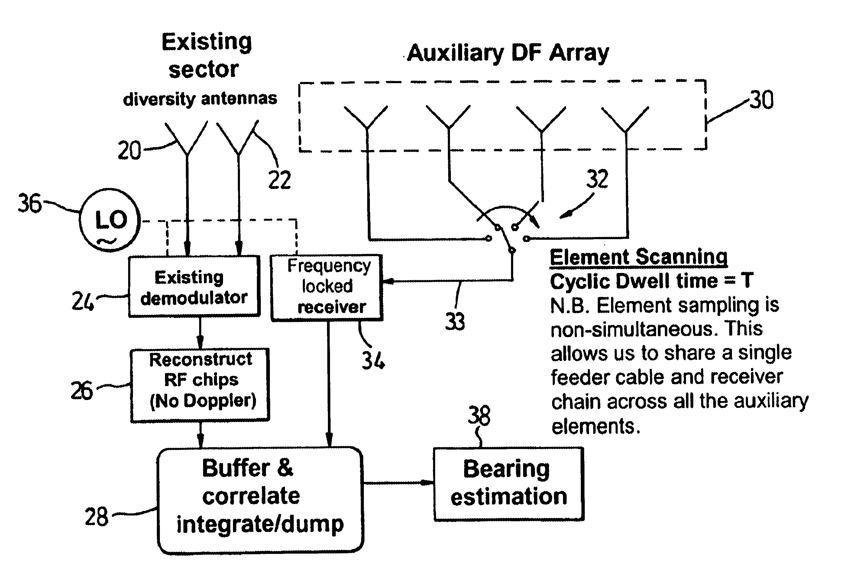
FIG. 3 is a block diagram of a cell site according to the embodiment of FIG. 2;

FIG. 4 illustrates the source of bearing bias due to Doppler frequency offset in a multi-element antenna sampled through a commutating switch as in a further embodiment of the invention;

FIG. 5 illustrates the correction of Doppler frequency spread according to a further embodiment of the invention;

FIG. 6 is a space-time spectrum plot for two multipath signals with different Doppler offsets and spreads and the same angle of incidence.

FIG. 7 illustrates a four-element thinned (non-constant element spacing) array according to a further embodiment of the invention;

FIG. 8 illustrates a direction-...


PUM


Abstract

In a cellular mobile telecommunications system the position of a mobile station can be estimated in terms of its bearing and range from a cell site. A multi-element direction finding antenna at the cell site receives signals from the mobile station and a receiver circuit estimates the bearing using the relative phase of signals received at different antenna elements and estimates the range by measuring round trip delay of signals to and from the mobile station. Motion of the mobile station can introduce errors into the bearing estimate due to frequency offset and frequency spread when element sampling is non-simultaneous. Compensation for these errors is introduced by using signal samples successively received at the same antenna element to estimate Doppler frequency offset and spread. It is necessary to ensure accurate calibration of the direction finding antenna and the receiver circuit. This is done by injecting calibration signals into the circuit near the antenna or into the antenna itself from a near field probe. Other aspects of calibration, such as antenna position, are calibrated using a remote beacon. A beacon emulating a mobile station but at a fixed, known location, or a beacon at an adjacent cell site may be used.

Description

This invention relates to a method and apparatus for locating the position of a mobile station (MS) in a mobile telecommunications system.DESCRIPTION OF THE PRIOR ARTIt is desirable in certain applications for an operator of a mobile telecommunications system such as a cellular telecommunications system to be able to identify the geographical position of an MS during communication with a base transceiver station (BTS) of the system. For example, the US Federal Communications Commission (FCC) has implemented a position location mandate requiring system operators to be able to locate MS position with less than 125 m error in 67% of cases in order to provide an E911 (emergency) position location service in IS-95 based systems in the North American cellular and PCS bands.A BTS may in principle locate the position of a MS by measuring the round-trip delay of a signal sent from the BTS to the MS and back (i.e. the elapsed time between transmission of a signal from the BTS and reception of...

Claims


Application Information

Patent Timeline
Patent Type & Authority Patents(United States)
IPC IPC(8): G01S1/00G01S1/02G01S3/14G01S3/02G01S5/12G01S3/48H01Q1/24G01S13/74G01S13/00G01S19/09G01S19/46
CPCG01S1/026G01S3/023G01S3/48G01S5/12H01Q1/246G01S13/74
Inventor BEVAN, DAVID DAMIAN NICHOLASHUDSON, JOHN EDWARDOVERBURY, FRANCIS GILESREED, CHRISTOPHER JOHNGALE, SIMON JOHN
Owner APPLE INC
Why Eureka
Try Eureka