Dual fuel power generation system

Inactive Publication Date: 2004-08-24
PHILLIPS 66 CO
View PDF4 Cites 49 Cited by
  • Summary
  • Abstract
  • Description
  • Claims
  • Application Information

AI Technical Summary

Benefits of technology

It is still a further object of the present invention to provide a dual fuel turbine power generation system which allows the source of fuel powering the turbine to be readily switched back and forth between a liquid fuel source and a gaseous fuel source with minimal operational and maint

Problems solved by technology

The dual fuel capability of combined cycle power plants requires additional construction, operation, and maintenance expenditures versus single fuel combined cycle power plants.
For example, in dual fuel combined cycle power plants, both the gaseous fuel and the liquid fuel must have

Method used


Image

  • Dual fuel power generation system
  • Dual fuel power generation system
  • Dual fuel power generation system

Examples


Embodiment Construction

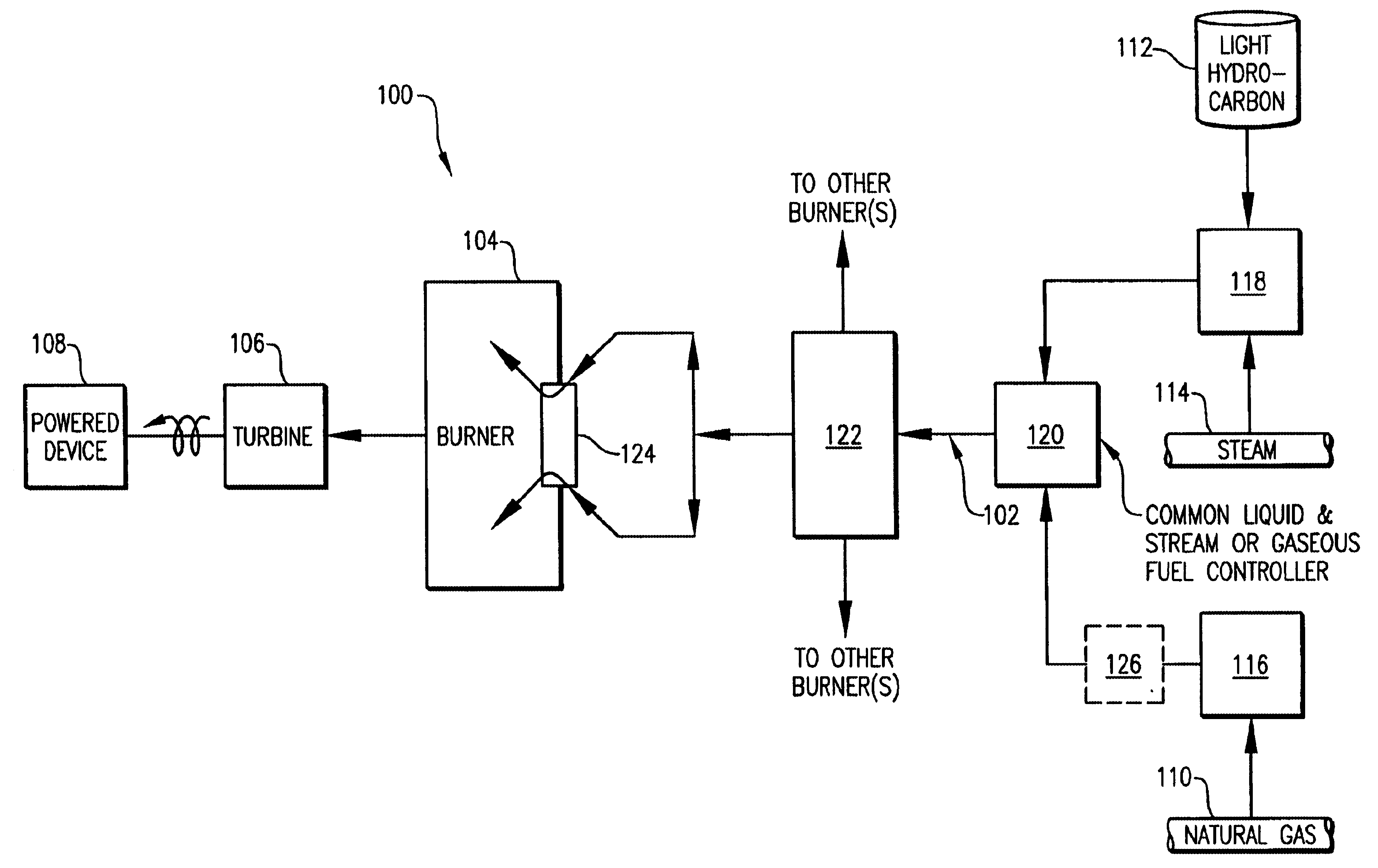
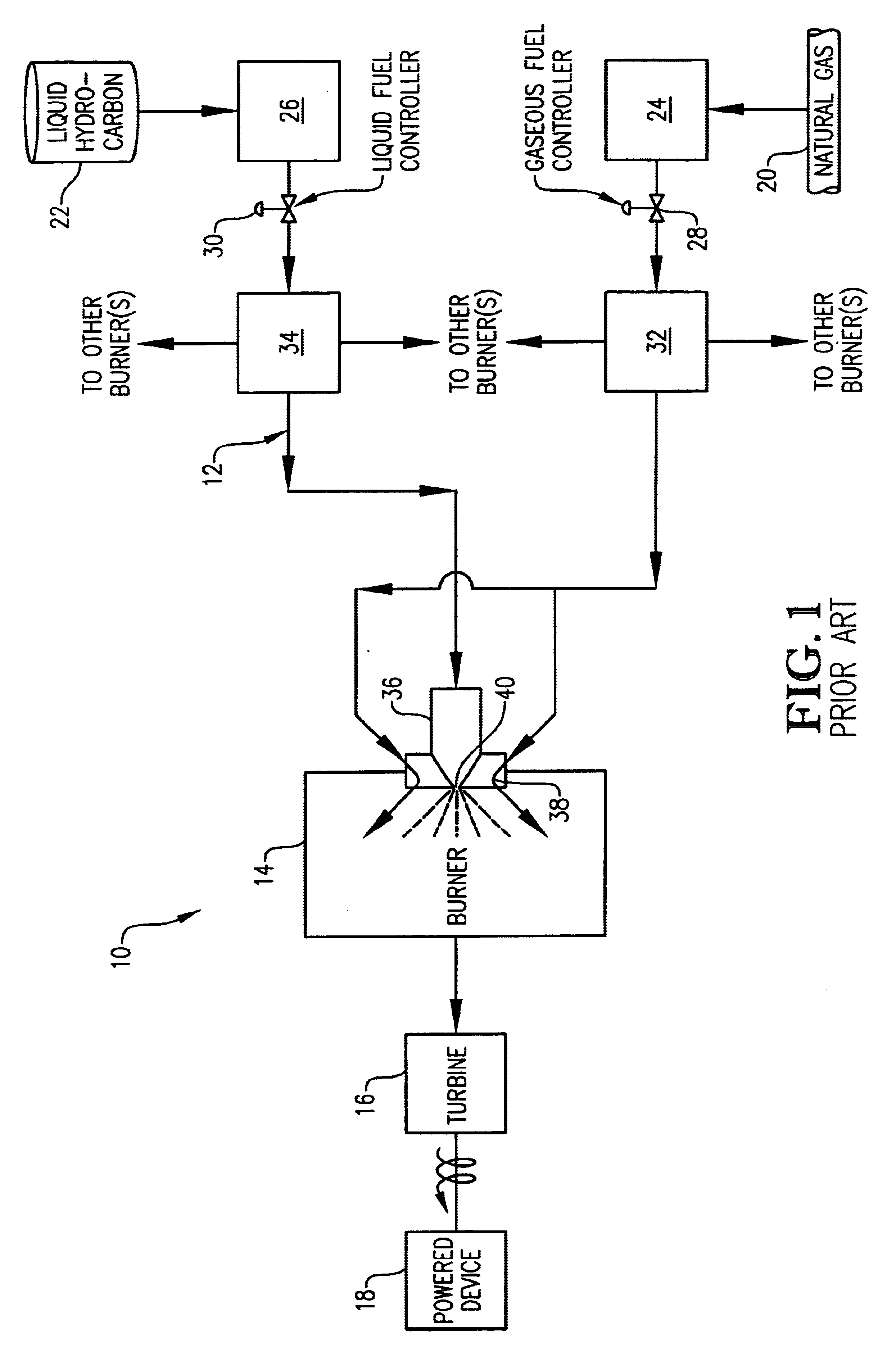
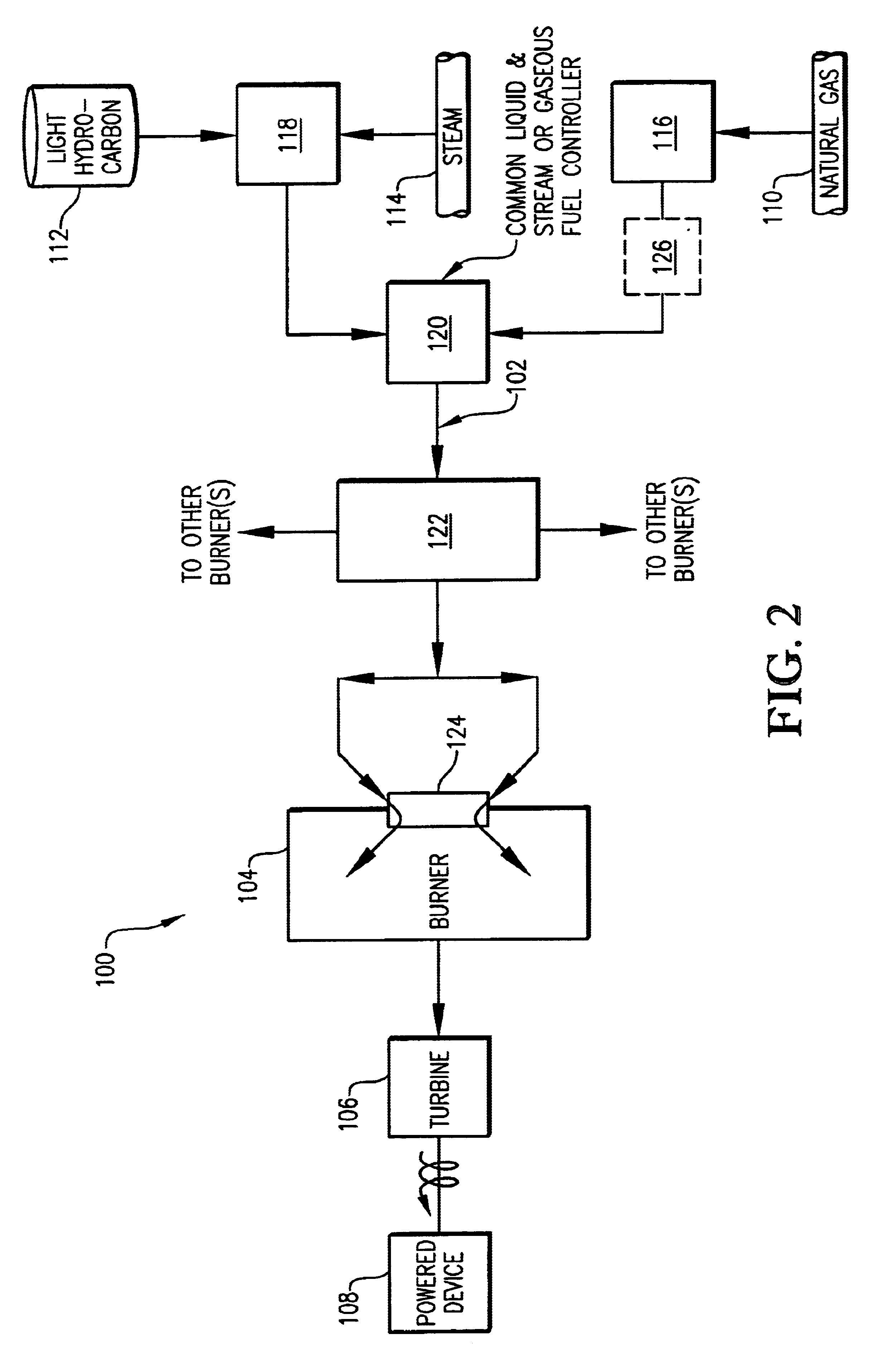
Referring initially to FIG. 1, a conventional power generation system 10 is illustrated as generally comprising a separate dual fuel delivery system 12, a burner 14, a turbine engine 16, and a powered device 18. Fuel delivery system 12 provides either a gaseous fuel or a liquid fuel to burner 14. In burner 14, the gaseous or liquid fuel is mixed with air and combusted. The combustion of the fuel in burner 14 powers turbine engine 16 which, in turn, mechanically powers powered device 18. Turbine engine 16 is typically a gas turbine employing in the range of from 5 to 20 individual burners 14. Most commonly, turbine engine 16 employs about 10 individual burners 14. Powered device 18 can be any device capable of converting mechanical energy into a more useful form such as, for example, electricity or pressurized fluid. Preferably, powered device 18 is an electrical generator or a fluid compressor. Fuel delivery system 12 generally comprises a gaseous fuel source 20, a liquid fuel sourc...


PUM


Abstract

A dual fuel power generation system employing a steam-mixed fuel and/or a gaseous fuel to power a turbine engine. The steam-mixed fuel is a gaseous mixture of a light hydrocarbon and steam. The steam-mixed fuel and gaseous fuel are delivered to the turbine engine (either individually or mixed) via a common fuel controller, a common fuel distribution system, and a common gas-only fuel nozzle.

Description

BACKGROUND OF THE INVENTION1. Field of the InventionThe present invention relates generally to dual fuel power generation systems employing one or more turbine engines. In another aspect, the invention concerns a dual fuel turbine system which can be powered by combusting natural gas and / or a gaseous fuel mixture of a light hydrocarbon and steam in the burner(s) of the turbine.2. Description of the Prior ArtCoal-fired electrical power generation plants typically have an operating efficiency of about 30 to about 40 percent. In contrast, combined cycle electrical power plants, employing gas turbine engines and heat recovery, typically have an operating efficiency of about 40 to about 60 percent. Combined cycle power plants are also much less expensive to design and build than coal-fired plants. Because of these and other advantages, combined cycle power plants have been employed worldwide to provide electrical power for commercial and residential use. Similarly, the gas turbine or com...

Claims


Application Information

Patent Timeline
IPC IPC(8): F02C3/22F02C3/24F02C3/30F02C9/00F02C3/20F02C9/40
CPCF02C3/22F02C3/24F02C3/30F02C9/40Y02E20/16
Inventor GERHOLD, BRUCE W.
Owner PHILLIPS 66 CO
Why Eureka
Try Eureka