System and method for non-contacting measurement of the eye

a non-contact measurement and eye technology, applied in the field of system and method for non-contact eye measurement, can solve problems such as errors influencing the choice of iol, and achieve the effect of reducing device-dependent measurement errors

Inactive Publication Date: 2004-08-24
CARL ZEISS JENA GMBH
View PDF25 Cites 72 Cited by
  • Summary
  • Abstract
  • Description
  • Claims
  • Application Information

AI Technical Summary

Benefits of technology

It is the primary object of the invention to reduce t

Problems solved by technology

Various errors influencing the choice of IOL c

Method used


Image

  • System and method for non-contacting measurement of the eye
  • System and method for non-contacting measurement of the eye
  • System and method for non-contacting measurement of the eye

Examples


Embodiment Construction

:

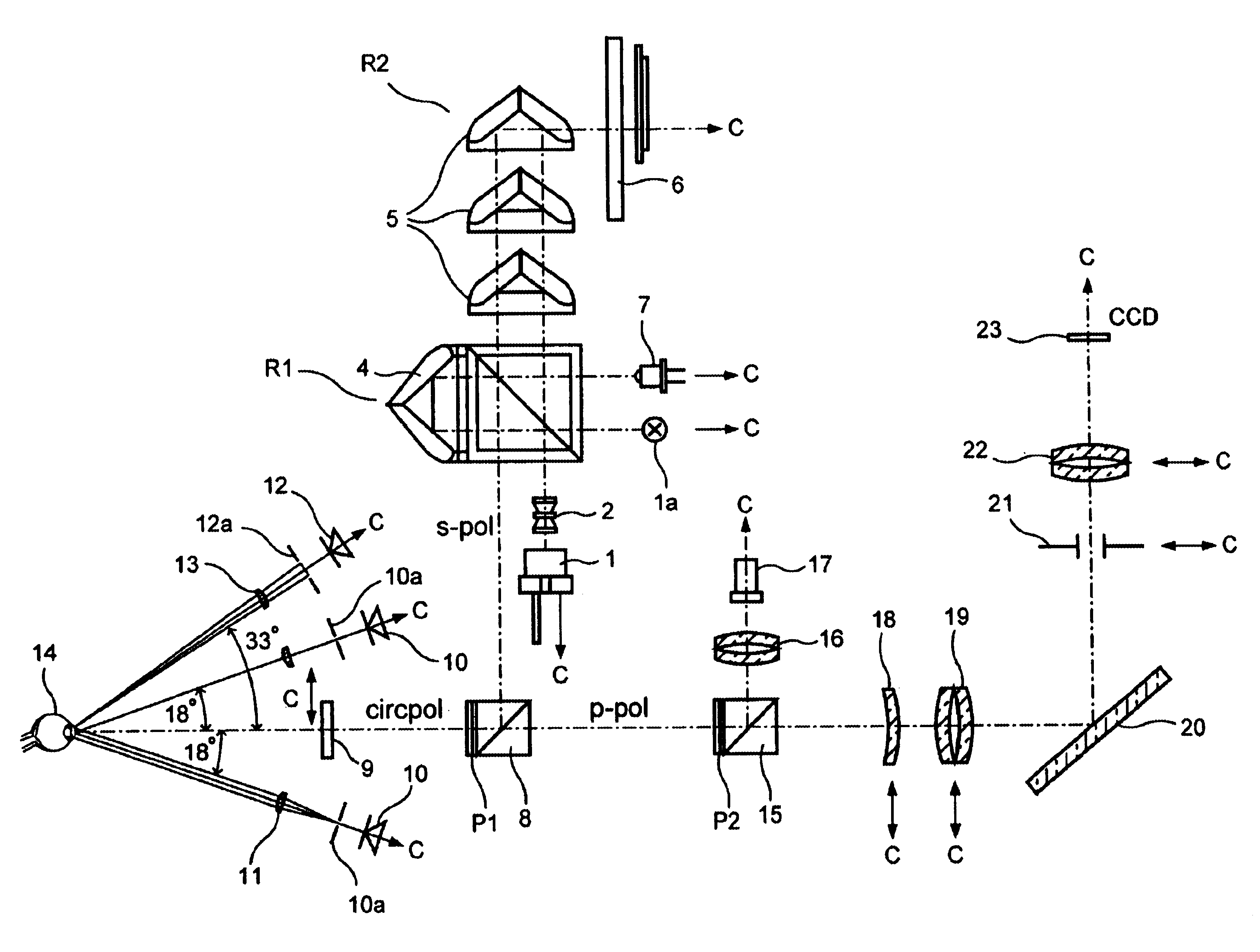
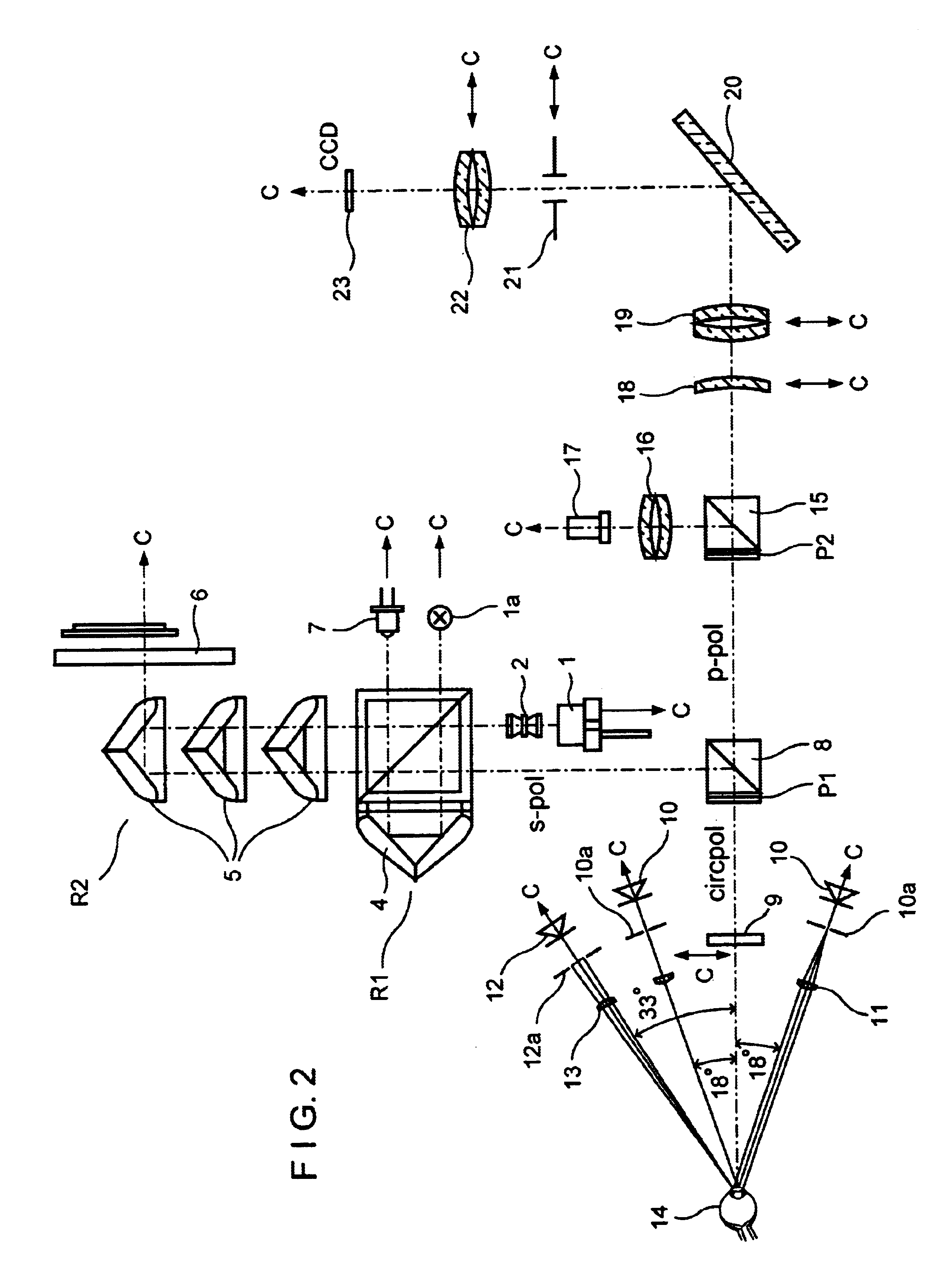
According to FIG. 5, a central control is provided for adjusting and controlling all adjustable units and optical elements such as optics 18, 19, 22, diaphragm 21, etc.

The different imaging scales taking into account the action of the DOE call for reversing processes in the device. These reversing processes are preferably carried out by means of motor and in a program-controlled manner.

A compact device has been realized in which the essential electronics building blocks are integrated. The heart of the device is an embedded Pentium controller C to which are connected a display D (showing the eye 14 being examined and a menu for the user), keypad, mouse, foot switch and printer as peripheral equipment.

ALM

The control of the laser diode 1 and interferometer slide IS (movable prism 5, connected with measuring system) is carried out via the controller C. To reduce the influence of eye movements, a short measuring time (less than 0.5 sec) must be realized. The signal generated by the APD...


PUM


Abstract

Combined equipment for non-contacting determination of axial length (AL), anterior chamber depth (VKT) and corneal curvature (HHK) of the eye are also important for the selection of the intraocular lens IOL to be implanted, particularly the selection of an intraocular lens IOL to be implanted, preferably with fixation of the eye by means of a fixating lamp and/or illumination through light sources grouped eccentrically about the observation axis.

Description

A longitudinal section through the human eye is shown schematically in FIG. 1. The axial length AL of the human eye is usually measured by a contact ultrasound method. Other measuring methods are described in DE 3201801, U.S. Pat. No. 5673096 and DE 4446183 Al. The curvature of the cornea-cornca radius HHR is determined by means of known keratometers / ophthalmometers (DD 251497, U.S. Pat. Nos. 4,572,628, 4,660,946, 5,212,507, 5,325,134). The measurement of the anterior chamber depth VKT can be carried out by ultrasound or by means of a unit added to a slit lamp (anterior chamber depth gauge, adjustment via the slit lamp image).These measurements, which are also important for selecting the intraocular lens IOL to be implanted, must be determined particularly before a cataract operation, but also to monitor the progress of schoolchildren's myopia and to detect aniseikonia. In clinical practice, it is common to measure these quantities by means of at least two devices (e.g., ultrasonic ...

Claims


Application Information

Patent Timeline
IPC IPC(8): A61B3/107A61B3/117A61B3/10A61B3/15A61B8/10
CPCA61B3/0025A61B3/107A61B3/0008A61B3/14A61B3/117A61B3/1005A61B8/10A61B3/158
Inventor BARTH, ROLANDBERGNER, ROLANDMUELLER, LOTHARSTEINMETZ, DIETMARSCHUBERT, SIEGFRIEDVOIGT, KLAUS-DITMARBEHRENDT, FRANKDIETZEL, BURKHARDDOERING, AXEL
Owner CARL ZEISS JENA GMBH
Why Eureka
Try Eureka