Distributing ATM cells to output ports based upon destination information using ATM switch core and IP forwarding

a technology of atm switch core and destination information, applied in the direction of electrical equipment, data switching network, digital transmission, etc., can solve the problems of disturbing an increase in throughput, low processing speed of such processes, and large number of vcs required for forming cut-through paths

Inactive Publication Date: 2004-08-24
KK TOSHIBA
View PDF16 Cites 60 Cited by
  • Summary
  • Abstract
  • Description
  • Claims
  • Application Information

AI Technical Summary

Benefits of technology

FIG. 62 is a diagram showing the operation of the CSR upon receiving a cut-through trigger;
FIG. 63 is a diagram showing the operation of the CSR in a cut-through mode;
FIG. 64 is a diagram showing the shift operation from cut-through forwarding to hop-by-hop forwarding;

Problems solved by technology

Hence, the processing speed of such processes is low, and it can be a bottleneck in a network of a plurality of relay devices considering recent trend for higher-speed, heavier communication traffic, thus disturbing an increase in throughput.
However, when only the method of generating a cut-through path upon arrival of each application flow, i.e., only the flow-driven scheme is used, and such scheme is applied to a large-scale network, the number of VCs required for forming cut-through paths may become very large.
However, when only the topology-driven scheme is used, if quality control, e.g., band control is to be made, the bandwidth required when the traffic (data flow) volume is relatively heavy must be prepared between neighboring nodes.
That is, the network administrator must prepare for cut-through paths having different QOS classes, thus wasting the bandwidth.
Upon implementation by VP base, the maximum number of paths that one node can set is 256 (=2.sup.8), and the network has poor expandability.
Even when the CSR scheme is adopted, if hop-by-hop forwarding is concentratedly done by a single processor or a single (signal processing) hardware device, when the data volume from each ATM switch becomes larger in a future high-speed, large-capacity network, hop-by-hop forwarding traffic increases due to an increase in packet traffic, thus bottlenecking communications.
Also, since high operation speed and large-capacity processing performance (e.g., address search processes and the like) are required accordingly, cost may increase.
Hence, the processing load upon managing and controlling the ATM switch and IP processing unit becomes also heavy.
In this manner, the conventional ATM relay device concentratedly makes IP packet, signaling, and management and control communications using a single physical path between the ATM switch and IP processing unit, the software processing load concentrates on an IP relay device, and the forwarding bandwidth itself of IP packets is narrowed down, resulting in poor efficiency of an IP packet relay process.
Furthermore, in a future high-speed, large-capacity network, hop-by-hop forwarding traffic is projected to increase due to an increase in packet traffic, thus bottlenecking communications.
However, the conventional ATM relay device cannot meet such requirements.
The conventional ATM relay device processes by software (CPU processes) traffic which is not cut-through forwarded in the CSR scheme, i.e., packets forwarded hop by hop, resulting in considerably low processing performance.
For this reason, the VPI / VCI resources are wasted.
This problem becomes more serious as the network scale increases and the number of terminals increase.
That is, VPI / VCI resources are wasted.
When data of one packet is long or when cells that form the packet have a large interval, a long time is required for passing the first packet, and the second packet cannot be readily forwarded.
However, when a connection is released by such method, the time elapsed from when the current counter value has been reached until the processor polls cannot be detected.
Hence, the connection release timing may delay due to the difference between the cell passage timing and polling timing.
For this reason, although the connection is not used in practice, it cannot be corrected for a long period of time in proportion to the polling period of the passage cell counter for the specific connection.
That is, connection resources cannot be effectively used.
Such problem arises from a long polling period of the passage cell counter for a specific connection when the number of connections to be managed is large, since the processor controls the entire ATM switch.
However, in such method, control among processors is complicated very much.
For this reason, discarded packets may adversely influence control between the relay devices, and sharing of management information between the relay devices.
However, when the administrator sets cut-through trigger information in accordance with a request from the user, it is difficult for him or her to determine if that request actually reduces the load on the router and is effective for the network.
Confirming whether or not cut-through forwarding is effectively working after the cut-through trigger information is set can become a heavy load on the administrator.
For example, if it is set to enable cut-through even upon forwarding a few packets, the delay produced by the process for shifting the control to the cut-through mode may exceed the time saved by the cut-through mode.
In order to design effective cut-through trigger information, the actual IP packet forwarding state must be sufficiently taken into consideration, but it is very hard to do so.
This poses a problem in a router that uses the label switching technique including CSR.
However, in an ATM-LAN that needs only QOS (Quality of Service) assurance and resource management levels as low as a conventional LAN, and requires large-capacity lines of ATM and high switching speed, a large number of pieces of unwanted information must be saved in the routing table.

Method used


Image

  • Distributing ATM cells to output ports based upon destination information using ATM switch core and IP forwarding
  • Distributing ATM cells to output ports based upon destination information using ATM switch core and IP forwarding
  • Distributing ATM cells to output ports based upon destination information using ATM switch core and IP forwarding

Examples


first embodiment

The first embodiment of the present invention will be described in detail below with reference to the drawings.

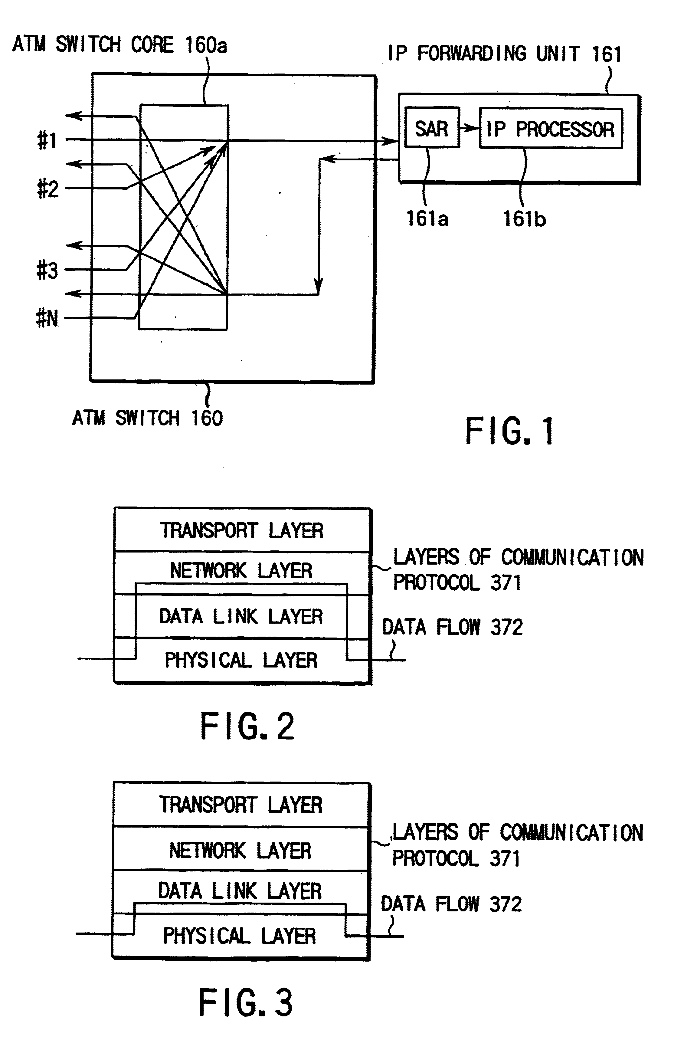
FIG. 18A is a diagram showing the arrangement on the input side of an ATM relay device according to the first embodiment of the present invention. This ATM relay device comprises a mechanism for searching for a destination IP address by hardware as an IP forwarding function.

The arrangement shown in FIG. 18A is basically constructed by an ATM switch 110 and an IP forwarding unit 120 connected to the output side of the ATM switch.

The ATM switch 110 includes an ATM switch core 111 which has a plurality of input ports, and distributes cells to output queues in units of destinations (VPI / VCI) of ATM cells, and a PerVC queuing unit 112 which has VC (virtual connection) queues #1 to #N, and stores cells in queues corresponding to the respective VCs in the respective output ports.

The IP forwarding unit 120 is constructed by a plurality of IP forwarding sections #1 (120-1) to #N (12...

second embodiment

The second embodiment of the present invention will be described in detail below with reference to the drawings.

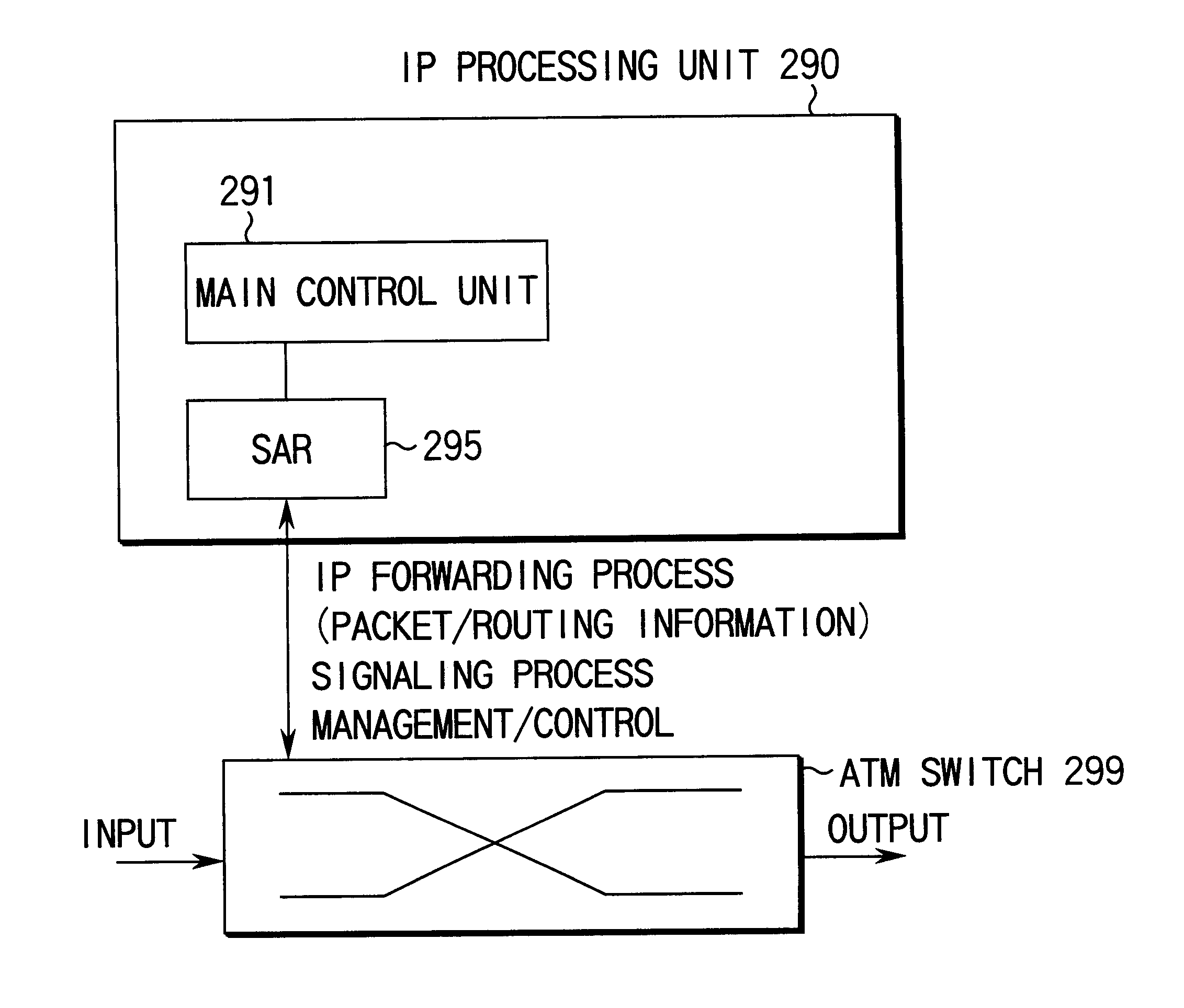
FIG. 24 is a diagram showing the arrangement of an ATM relay device according to the second embodiment of the present invention. The ATM relay device according to this embodiment comprises an IP forwarding function of forwarding IP packets hop by hop by searching for destination IP addresses.

Referring to FIG. 24, an IP processing unit 200 is connected to the output side of an ATM switch 250. The IP processing unit 200 comprises an IP forwarding processing function 202 of performing forwarding processes of IP packets such as hop-by-hop forwarding and the like, a signaling processing function 203 of setting a communication path, a management / control function 204 of managing and controlling the ATM switch 250, SARs 205, 206, and 207 which are respectively connected to the IP forwarding function 202, signaling processing function 203, and management / control function 204, and s...

third embodiment

The third embodiment of the present invention will be described in detail below with reference to the drawings.

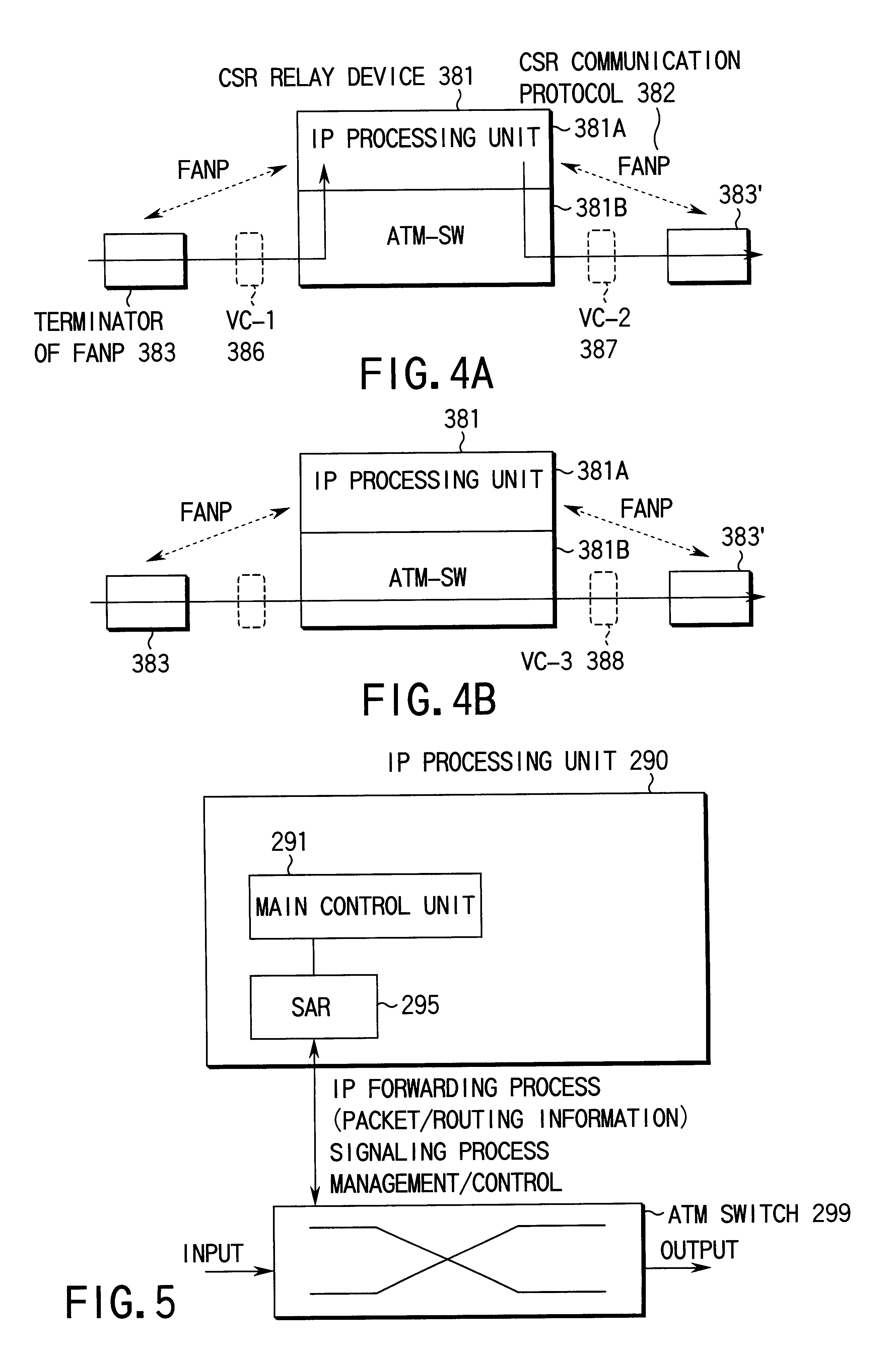
FIG. 29 is a diagram showing the schematic arrangement of a CSR relay device to which an ATM relay device according to the third embodiment of the present invention is applied. In the arrangement of this embodiment, an ATM switch 342 is connected to an IP processing unit 361 via a link 363 with IP processing for signaling and also via a link 344 with IP processing for forwarding, which is physically different from the link 363 with IP processing for signaling. That is, a path for forwarding processing (in this case, hop-by-hop forwarding) is physically different from that for signaling processing.

More specifically, the ATM switch 342 is connected to a cell / data unit segmentation and reassembly unit (to be referred to as a signaling SAR hereinafter) 362 via a signaling cell route 346, and the signaling SAR 362 is connected to a software processing unit 352 including a CPU vi...


PUM


Abstract

This invention has as its object to provide an ATM relay device which attains high-speed, large-capacity packet relaying by distributing the load on an IP forwarding unit without having to improve the operation speed, processing performance, and the like of an IP forwarding function. This invention has an ATM switch core (111) for distributing input ATM cells to corresponding ones of a plurality of output ports on the basis of their destination information. A plurality of IP forwarding units (120-1 to 120-n), which are provided in correspondence with the respective output ports of the ATM switch core (111) and have unique forwarding processing functions, execute predetermined forwarding processes for packets obtained by reassembling ATM cells input via the respective output ports. An SAR 121 assigns destination information that assumes different values in units of packets to ATM cells, which form each of packets having an identical address of those processed by the plurality of IP forwarding units (120-1 to 120-n). The ATM cells of a packet assigned identical destination information by the SAR 121 are stored in a PerVC queuing unit 112 by a predetermined volume, and are output in the format that stores the ATM cells by the predetermined volume.

Description

The present invention relates to an ATM relay device which constructs an IP relay function in a packet communication scheme represented by TCP / IP or the like using destination information on the basis of ATM (Asynchronous Transfer Mode), and a network including it.With growth of the Internet, the Internet infrastructure keeps on developing. An important technique in this respect is a device for connecting a plurality of logical networks. A packet relay device such as a bridge, router, or the like forwards packets by routing in units of packet destinations in the data link layer in case of communications within a given subnet (logical network) or in the network layer in case of communications between different subnets (logical networks).Packet relay using ATM uses a packet forwarding scheme called hop-by-hop forwarding. FIG. 1 is a diagram showing the arrangement of such conventional ATM relay device, which comprises an ATM switch 160 which includes an ATM switch core 160a having a p...

Claims


Application Information

Patent Timeline
Patent Type & Authority Patents(United States)
IPC IPC(8): H04L12/56H04L29/06H04L12/54H04L49/111
CPCH04L12/5601H04L12/5693H04L47/621H04L47/6215H04L47/6225H04L49/108H04L49/256H04L49/309H04L2012/5651H04L2012/5658H04L2012/5667H04L69/16H04L47/50
Inventor NOGAMI, KAZUOHORIGUCHI, AKIHIROHIRAI, KEITAROMORI, KAZUAKIIKEDA, TAKASHITAKAHASHI, JUNICHIKISHIGAMI, TOHRUWATANABE, MASANORI
Owner KK TOSHIBA
Why Eureka
Try Eureka