

Electromagnetic wave absorber
a technology of electromagnetic absorbers and carbon absorbers, which is applied in the direction of magnetic materials, magnetic bodies, instruments, etc., can solve the problems of remarkably troublesome production of carbon absorbers of 1.5 to 2 m in height, noise interference in the operation of the electronic device itself or other devices, and the limited size of the member used for supporting the absorber or applying it to the anechoic chamber
- Summary
- Abstract
- Description
- Claims
- Application Information
AI Technical Summary
Benefits of technology
Problems solved by technology
Method used
Image

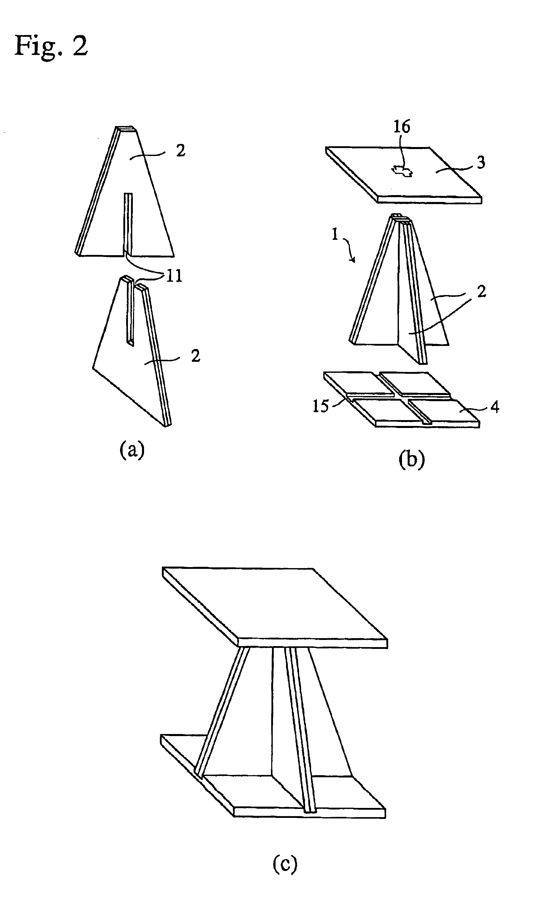
Examples
example 2
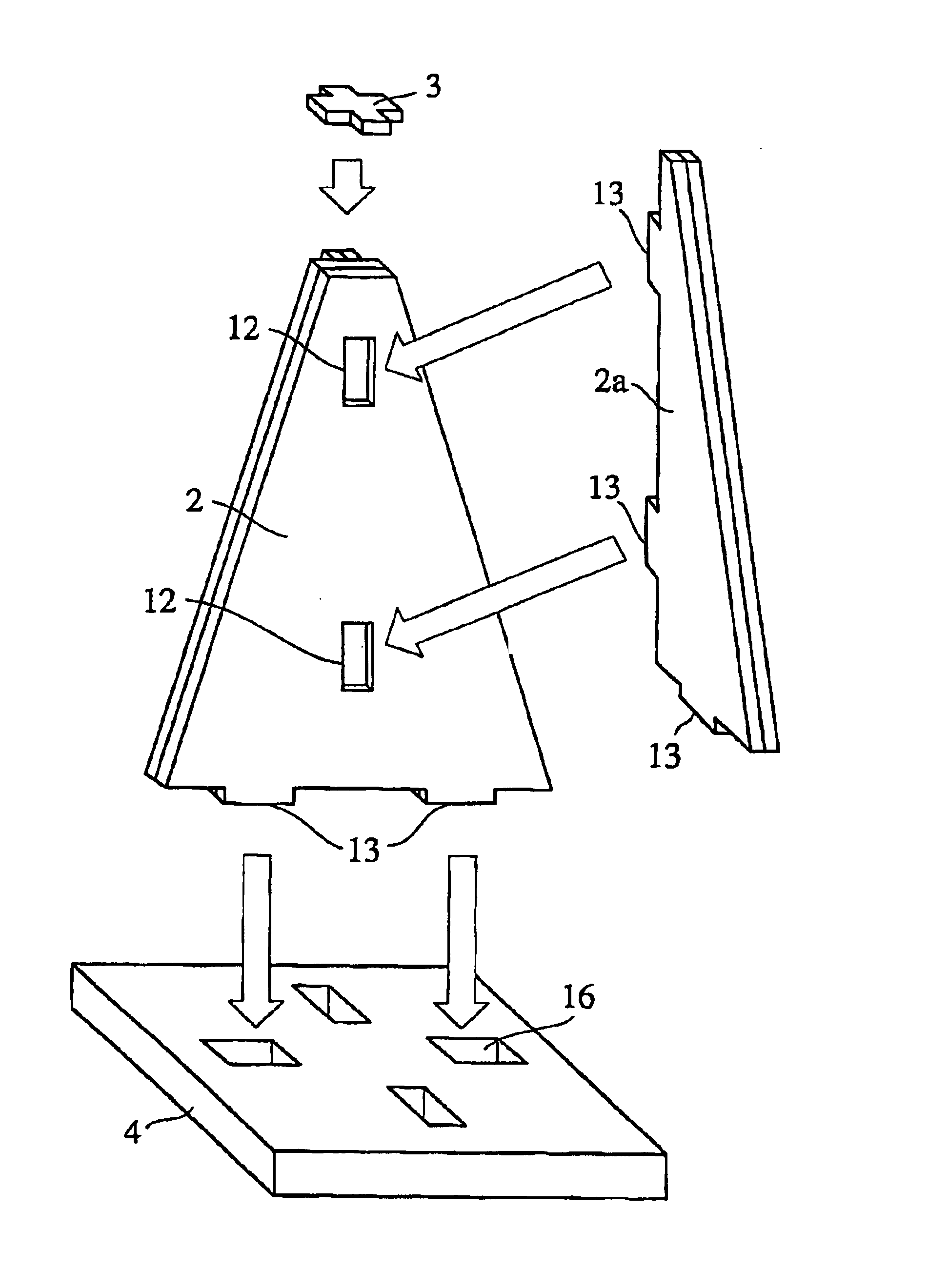
The non-combustible plate prepared in EXAMPLE 1 was cut into two trapezium-shaped plates each having an upper base of 40 mm, a lower base of 300 mm and a height of 1200 mm. At the center of one trapezium-shaped plate were provided two fitting-apertures 12 and at the bottom thereof were provided two convex portions 13 to be inserted into openings 16 of the base plate 4, and the other trapezium-shaped plate was split in two and at the side and bottom thereof were provided convex portions 13, whereby wave-absorbing plates 2 and 2a shown in FIG. 3 were prepared. The convex portions 13 of the wave-absorbing plate 2a were fitted into the fitting-apertures 12 of the wave-absorbing plate 2, and an upper plate 3 and a base plate 4 were disposed on the resultant wave-absorbing body in the same manner as in EXAMPLE 1 to obtain an electromagnetic wave absorber. Incidentally, the upper plate 3 used in EXAMPLE 2 was in a cross-shape suitable for the shape of the top of the wave-absorbing body.
In ...
example 3
Six wave-absorbing plates 5 shown in FIG. 5(a), which were in a shape of continuously connected three triangles with a base of 200 mm and a height of 450 mm each having notches 11 with a width of 22.5 mm in the top or the center of the bottom, were prepared of the non-combustible plate obtained in EXAMPLE 1. The notches 11 of the wave-absorbing plates 5 were engaged each other, such that the wave-absorbing plates 5 are made integral in a lattice pattern. On the bottom of the resultant wave-absorbing body having a shape of continuously connected, partially overlapping pyramids was disposed a base plate 4 to obtain an electromagnetic wave absorber shown in FIG. 5(b).
A plurality of absorbers are needed when a conventional electromagnetic wave absorber with a small base area is applied to a predetermined area, thereby increasing production steps and costs. For example, in a case where a pyramid-shaped absorber is applied to an area of 60 cm around, only one absorber is needed when it ha...
example 4
Four wave-absorbing plates 6 shown in FIG. 6, which were in a shape of triangle with a base of 300 mm and a height of 450 mm having a notch 11 with a width of 22.5 mm in the center of the base, were prepared of the non-combustible plate obtained in EXAMPLE 1. The wave-absorbing plates 6 and the wave-absorbing body 1 formed in the same manner as in EXAMPLE 1, which was provided notches 11 of 22.5 mm in width on each hypotenuse, were engaged each other through the notches, and a base plate 4 was disposed on the bottom thereof to obtain an electromagnetic wave absorber.
PUM
| Property | Measurement | Unit |
|---|---|---|
| height | aaaaa | aaaaa |
| thickness | aaaaa | aaaaa |
| thickness | aaaaa | aaaaa |
Abstract
Description
Claims
Application Information