Multiphase clamp coupled-buck converter and magnetic integration

a converter and clamp coupled technology, applied in the direction of dc-dc conversion, power conversion systems, instruments, etc., can solve the problems of increasing clock speeds, increasing dispersed power, and imposing challenges in the design of power supplies by microprocessors

Inactive Publication Date: 2004-08-31
VIRGINIA TECH INTPROP INC
View PDF3 Cites 172 Cited by
  • Summary
  • Abstract
  • Description
  • Claims
  • Application Information

AI Technical Summary

Problems solved by technology

Advances in microprocessor technologies impose challenges in designing power supplies.
However, to exploit the reduced signal propagation time, clock speeds have been increased; increasing dissipated power.
It can be seen that at small duty cycles where the current ripple reduction is poor, the benefits of increasing the number of phases of the buck converter is compromised, as well.
Therefore, higher differential input and output voltages result in higher switching losses and reduced efficiency.
The problem and criticality of efficiency is also compounded since reduced efficiency implies increased power dissipation of the VRM in the physical proximity to the load / microprocessor (to limit ohmic voltage drop) increases the complexity and criticality of heat removal from both the VRM and the load.
Perhaps more importantly, however, the increased ripple voltage / current at short duty cycles compromises transient response of the VRM.

Method used


Image

  • Multiphase clamp coupled-buck converter and magnetic integration
  • Multiphase clamp coupled-buck converter and magnetic integration
  • Multiphase clamp coupled-buck converter and magnetic integration

Examples


Embodiment Construction

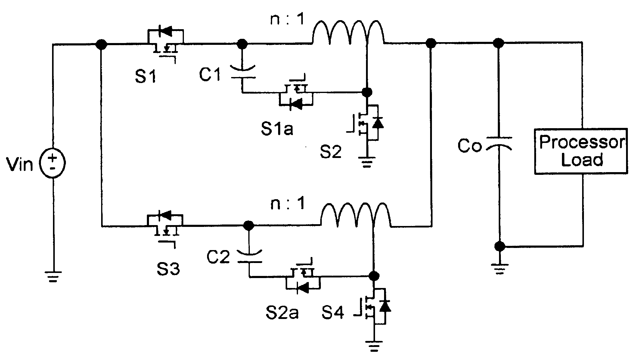
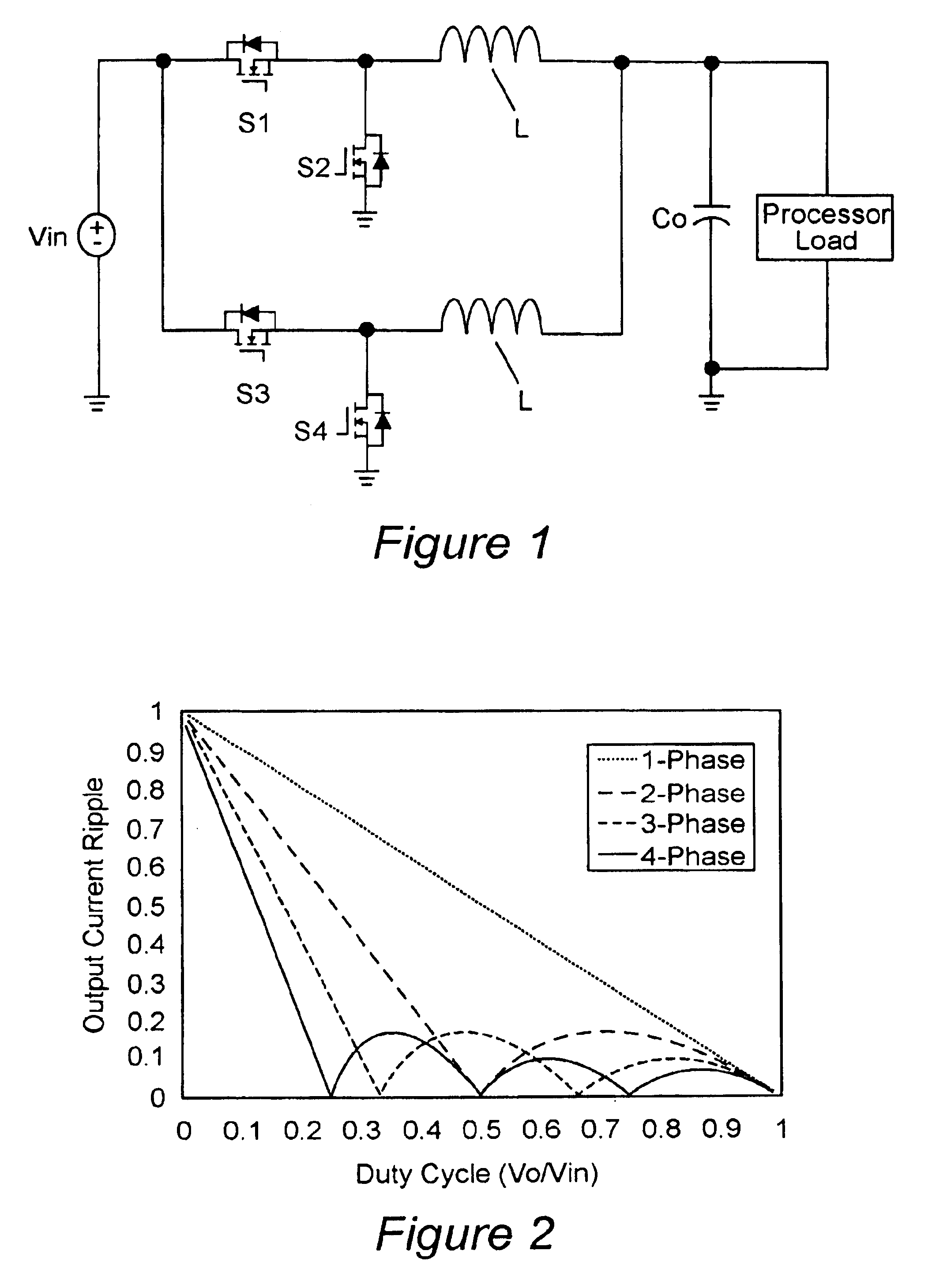
Referring now to the drawings, and more particularly to FIG. 1, there is shown a schematic diagram of an exemplary multiphase buck converter suitable for supplying power to a semiconductor integrated circuit load such as a microprocessor. It should be understood that while FIG. 1 does not include the invention, it is, nevertheless, provided and arranged to facilitate an understanding of the invention and no portion thereof is admitted to be prior art as to the present invention. A two-phase buck converter is illustrated for simplicity but more phases can be provided if desired.

It will be appreciated by those skilled in the art that capacitor C.sub.0 is a filter capacitor capable of supplying current, including transient current levels to the load while maintaining voltage substantially constant. The value of the capacitance will thus depend on the magnitude of the ripple voltage, current requirements of the load and the voltage tolerance of the load and it is usually desirable to mi...


PUM


Abstract

Voltage regulation, transient response and efficiency of a voltage regulator module (VRM) is improved where short duty cycles are necessitated by large differentials of input and output voltage by including at least one clamping of a tap of an inductance in series with an output of each of a plurality of parallel branches or phases which are switched in a complementary fashion or providing coupling between inductors of respective phases. Such coupling between inductors is achieved in a small module with an integrated magnetic structure. Reduced component counts are achieved while deriving built-in input and output filters. Principals of the invention can be extended to isolation applications and push-pull forward converts, in particular. A lossless clamping circuit is also provided allowing spike currents to be suppressed while returning power to the output of the VRM.

Description

1. Field of the InventionThe present invention generally relates to power supplies and DC to DC converters and, more particularly, to multiphase power supplies and converters which operate at low output voltages and increased input to output voltage differentials.2. Description of the Prior ArtAdvances in microprocessor technologies impose challenges in designing power supplies. In particular, there has been a strong incentive to develop increased integration density since increases in performance in terms of signal propagation time, noise immunity, increased functionality per chip and the like can be achieved thereby as well as some improvements in manufacturing economy. However, to exploit the reduced signal propagation time, clock speeds have been increased; increasing dissipated power. As a consequence, to limit power dissipation, operating voltages have been decreased in modern designs and further reduction in operating voltage can be anticipated. At the same time, supply volta...

Claims


Application Information

Patent Timeline
Patent Type & Authority Patents(United States)
IPC IPC(8): H02M3/158H02M3/04
CPCH02M3/158H02M3/1584H02M2001/0064H02M1/0064
Inventor XU, PENGYAO, KAIWEILEE, FRED C.YE, MAOWEI, JIA
Owner VIRGINIA TECH INTPROP INC
Why Eureka
Try Eureka