
Endoscope system

a technology of endoscope and endoscope, which is applied in the field of endoscope system improvement, can solve the problems of inability to accurately diagnose and require a relatively long time for diagnosis, and achieve the effect of accurate diagnosis within a relatively short period of tim

Inactive Publication Date: 2004-09-14
ASAHI KOGAKU KOGYO KK
View PDF4 Cites 182 Cited by
  • Summary
  • Abstract
  • Description
  • Claims
  • Application Information

AI Technical Summary

Benefits of technology

It is therefore an object of the present invention to provide an improved endoscope system that enables an accurate diagnosis within a relatively short period of time.

Problems solved by technology

However, the pathological inspection requires time, and therefore, the diagnosis requires relatively long time.
However, such a portion might be overlooked, and as a result, an accurate diagnosis may not be done even if the pathological inspection is performed.

Method used


Image

  • Endoscope system
  • Endoscope system
  • Endoscope system

Examples


Embodiment Construction

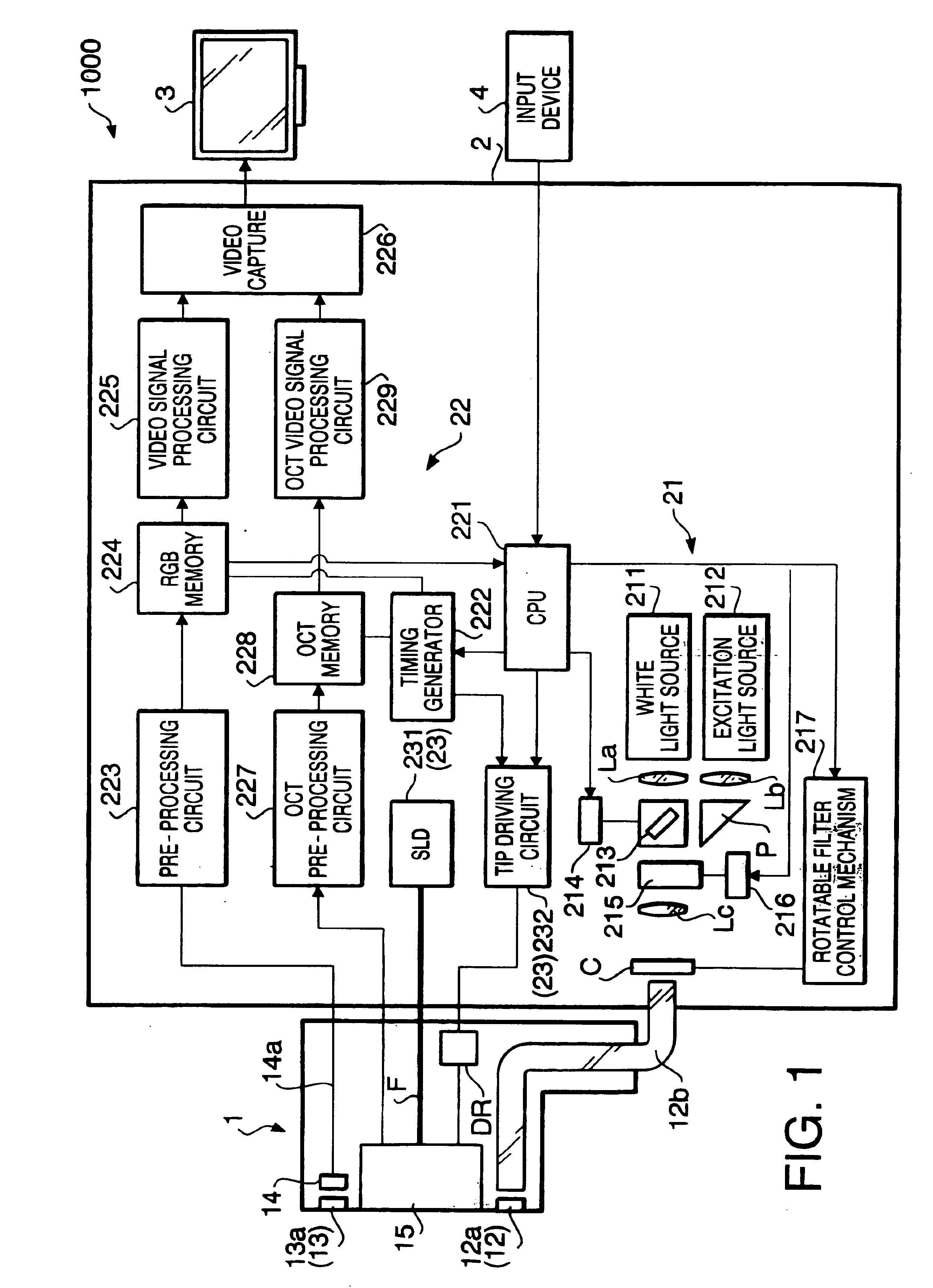
FIG. 1 shows an electronic structure of the endoscope system 1000 according to an embodiment of the invention.

As shown in FIG. 1, the endoscope system 1000 includes an endoscope 1, and external device 2 connected to the endoscope 1, a monitor 3 connected to the external device 2, and an input device 4.

The endoscope 1 includes an insertion tube having an elliptical cross section, and an operation unit which is connected to a proximal end of the insertion tube. Various operation switches are provided on the operation unit.

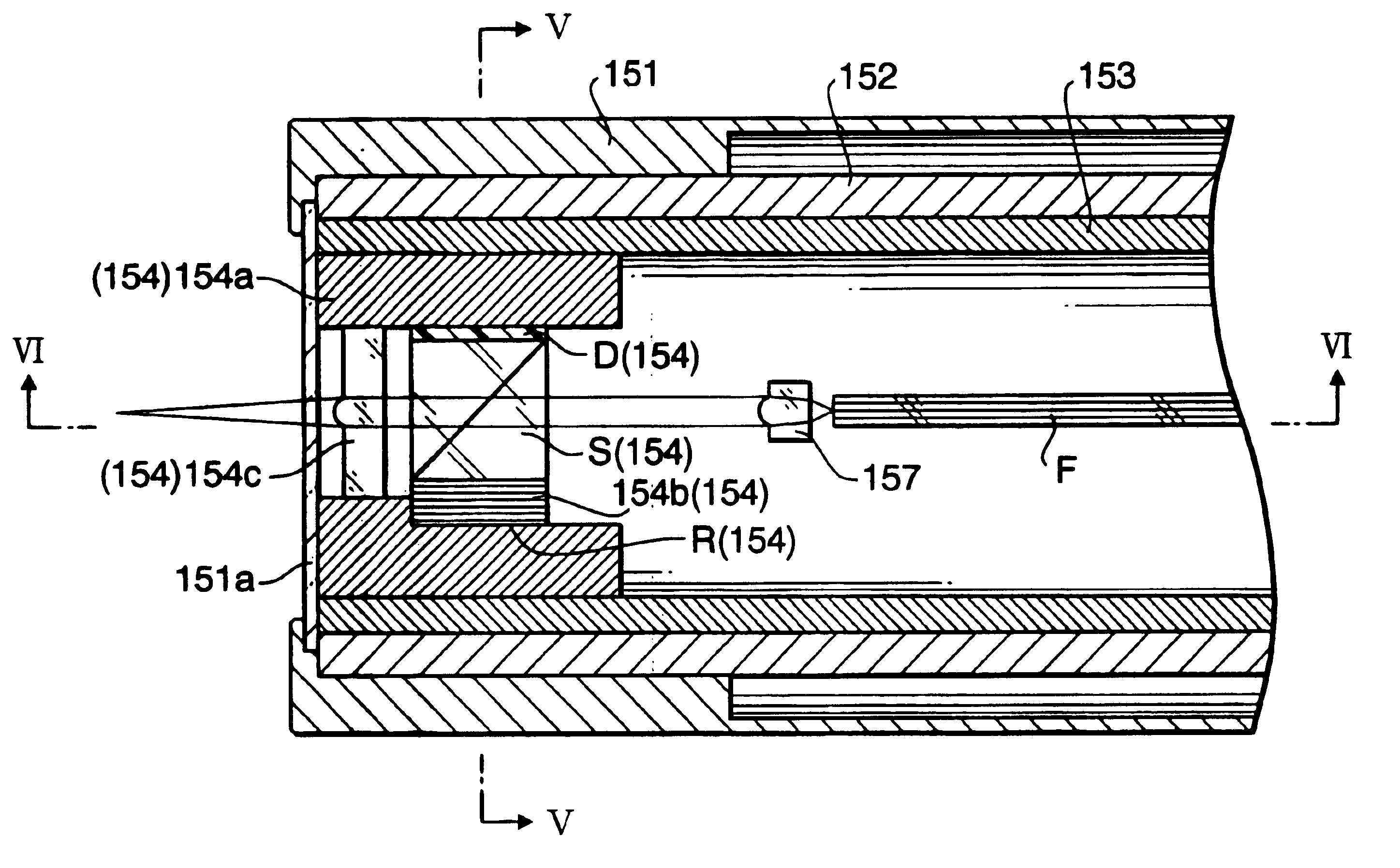
Inside the insertion tube of the endoscope 1, an illuminating optical system 12, an objective optical system 13, an image capturing system (e.g., CCD: charge coupled device) 14, and an OCT unit 15 are provided. The illuminating optical system 12 is provided with an illumination lens 12a secured at the tip end of the insertion tube, and a light guide fiber bundle 12b (hereinafter referred to as a light guide). The light guide 12b is inserted through the endoscope 1 an...


PUM


Abstract

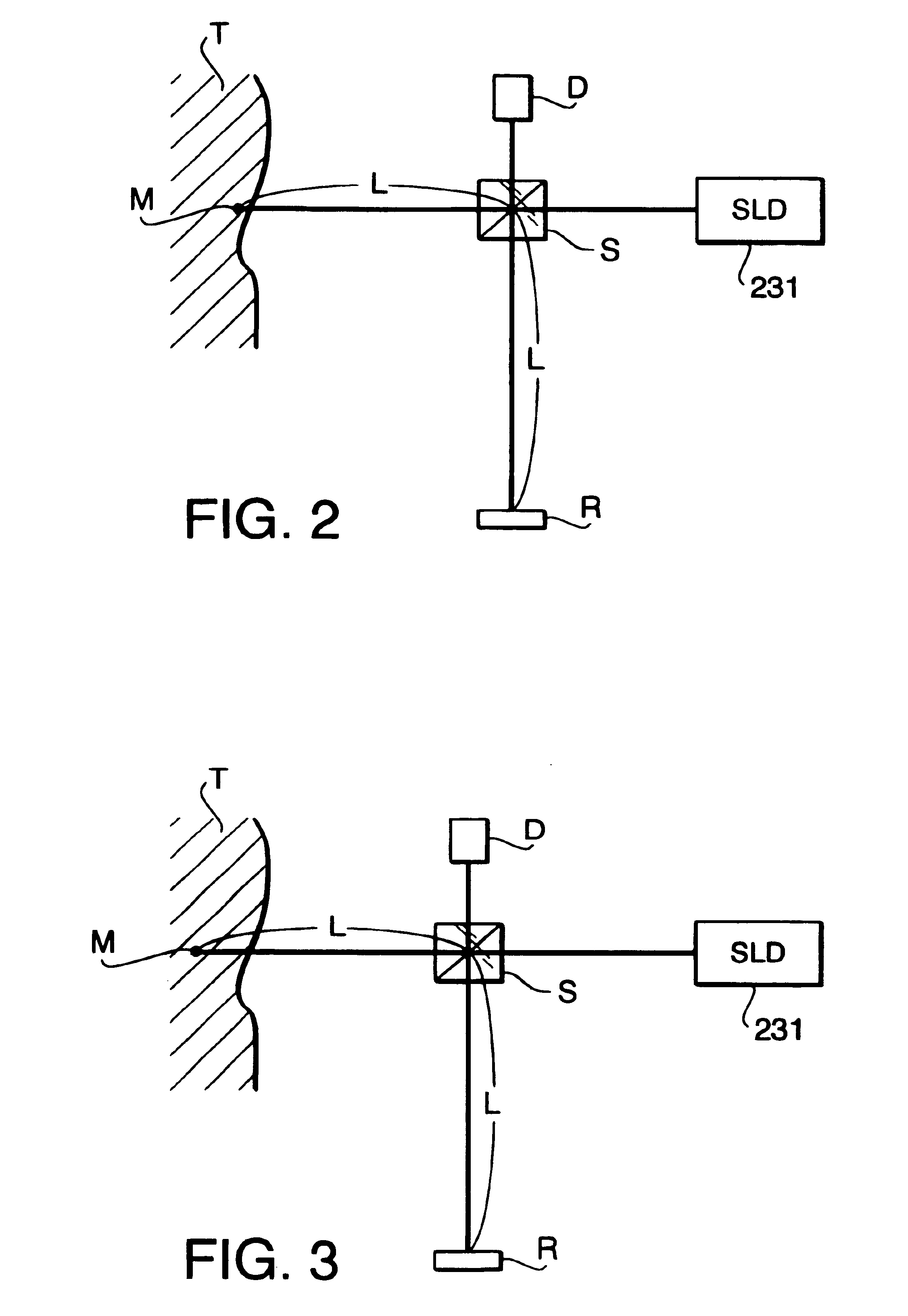
An endoscope system is provided with a light guide including a plurality of optical paths, and a low-coherent light source that emits a low-coherent light beams. The low-coherent light source is provided at a proximal end side of the light guide. The light beams emitted by the low-coherent light source are incident on the plurality of optical paths, respectively. The endoscope system is further provided with an interferometer unit. The interferometer unit includes a beam splitting element that splits each of the low-coherent beams emitted from the distal end of the light guide and emits split one of each of the beams to an object, a reference optical system that guides the other split beam of each of the beams, a reflector unit that reflects the beams guided by the reference optical system toward the beam splitting element, and a light detecting device that detects an interfered beam generated by interference, at the beam splitting element, between the beam reflected by the object and the beam reflected by the reflector unit. The endoscope system is further provided with a driving unit that moves the interferometer unit toward / away from the object, and a signal processing system that generates a tomogram based on signals detected by the light detecting device.

Description

The present invention relates to an endoscope system that is capable of capturing in vivo OCT (Optical Coherence Tomography) images of an object.Conventionally, endoscope systems for observing objects inside a human cavity have been known. Such an endoscope system is provided with an endoscope, which is to be inserted inside the human cavity, and an illuminative external device, which is to be connected to the endoscope. The external device includes a light source unit for illuminating the object and a processor for processing image signals.The endoscope includes:an illuminating optical system, which is connected to the light source unit of the external device and used for illuminating an object (e.g., the paries of a body cavity);an objective optical system for forming an optical image of the object; anda CCD (Charge Coupled Device) provided substantially at a focal plane of the objective optical system and electrically connected to the processor of the external device.At a tip end...

Claims


Application Information

Patent Timeline
IPC IPC(8): A61B1/06A61B1/04A61B1/07G02B23/24A61B1/00G01B11/00G01N21/17
CPCA61B5/0066G02B23/2423G02B23/2469A61B1/05A61B1/0638A61B1/0646
Inventor FURUSAWA, KOICHIEGUCHI, MASARUUTSUI, TETSUYANAKAMURA, TETSUYAOZAWA, RYOOKADA, SHINSUKE
Owner ASAHI KOGAKU KOGYO KK
Learn More