Passive water management fuel cell

a fuel cell and water management technology, applied in the direction of cell components, cell component details, separation processes, etc., can solve the problems of fuel cell freezing in cold climates, fuel cell production with the proper size pores is extremely expensive, and the enhancement of one harms the other, so as to achieve the effect of convenient manufactur

Inactive Publication Date: 2004-09-21
AUDI AG
View PDF5 Cites 25 Cited by
  • Summary
  • Abstract
  • Description
  • Claims
  • Application Information

AI Technical Summary

Benefits of technology

Objects of the invention include the separation of water management from cooling in a PEM fuel cell; a PEM fuel cell which can use antifreeze solutions as a coolant; PEM fuel cells which can utilize start-up solutions to assist in thawing, when frozen; PEM fuel cells which do not require high tolerance, fine pore porous reactant flow field plates; PEM fuel cells employing easily manufactured, low tolerance plates for reactant flow fields and / or water management.

Problems solved by technology

However, the production of water transport plates with the proper size pores is extremely expensive.
The utilization of larger pores for high water permeability while at the same time the utilization of smaller pores for high bubble pressure to prevent fuel reactant gas crossing over and mixing with the oxidant reactant gas, poses the dilemma; enhancement of one harms the other and vice versa.
One problem with water transport plates, which utilize pure fuel cell water as the coolant, is that such fuel cells will freeze in cold climates, when not operating.
Furthermore, the use of substances other than water in the water flow fields, to enhance thawing and initial startup, adulterates the fuel cell causing performance degradation.

Method used


Image

  • Passive water management fuel cell
  • Passive water management fuel cell
  • Passive water management fuel cell

Examples


Embodiment Construction

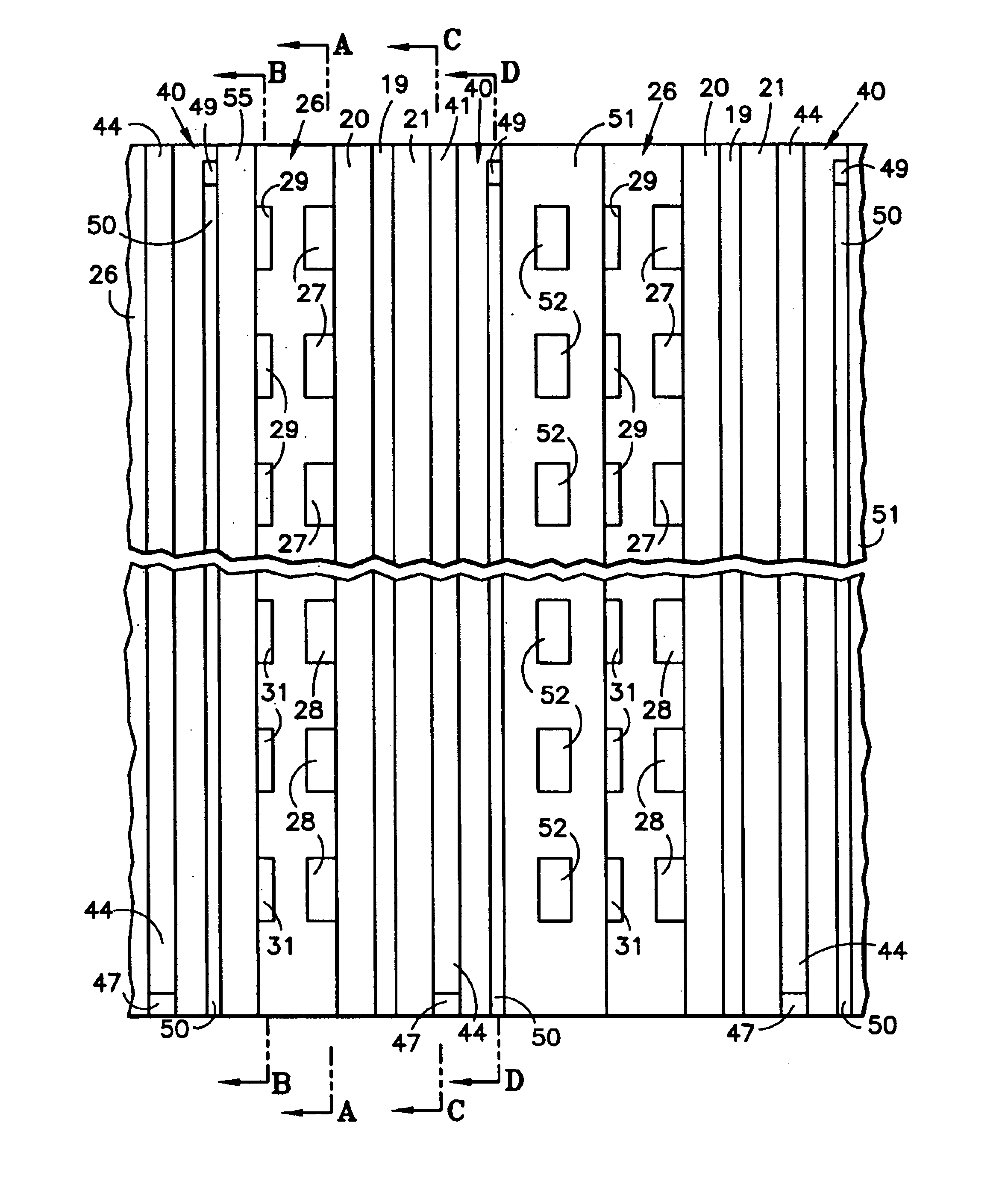
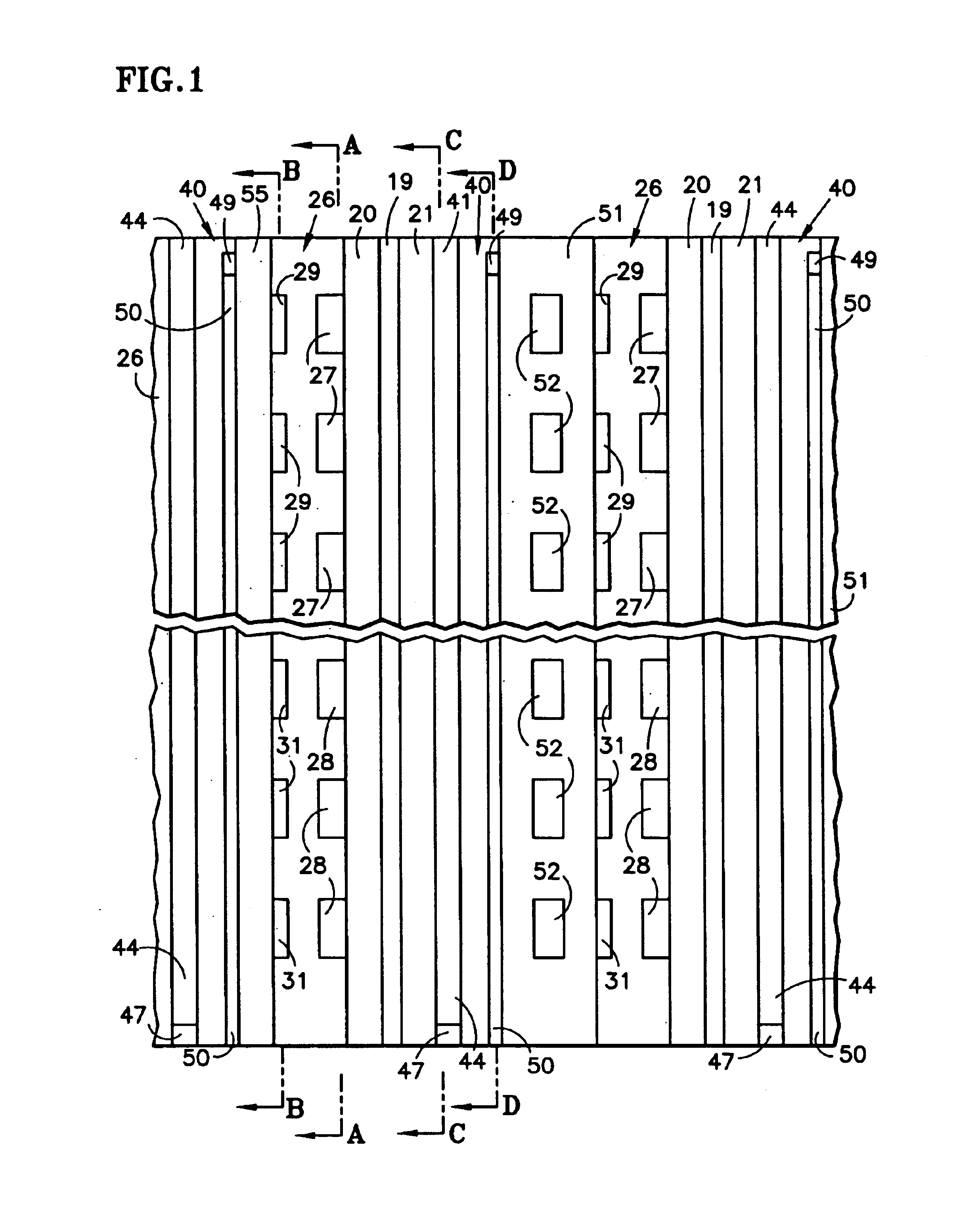
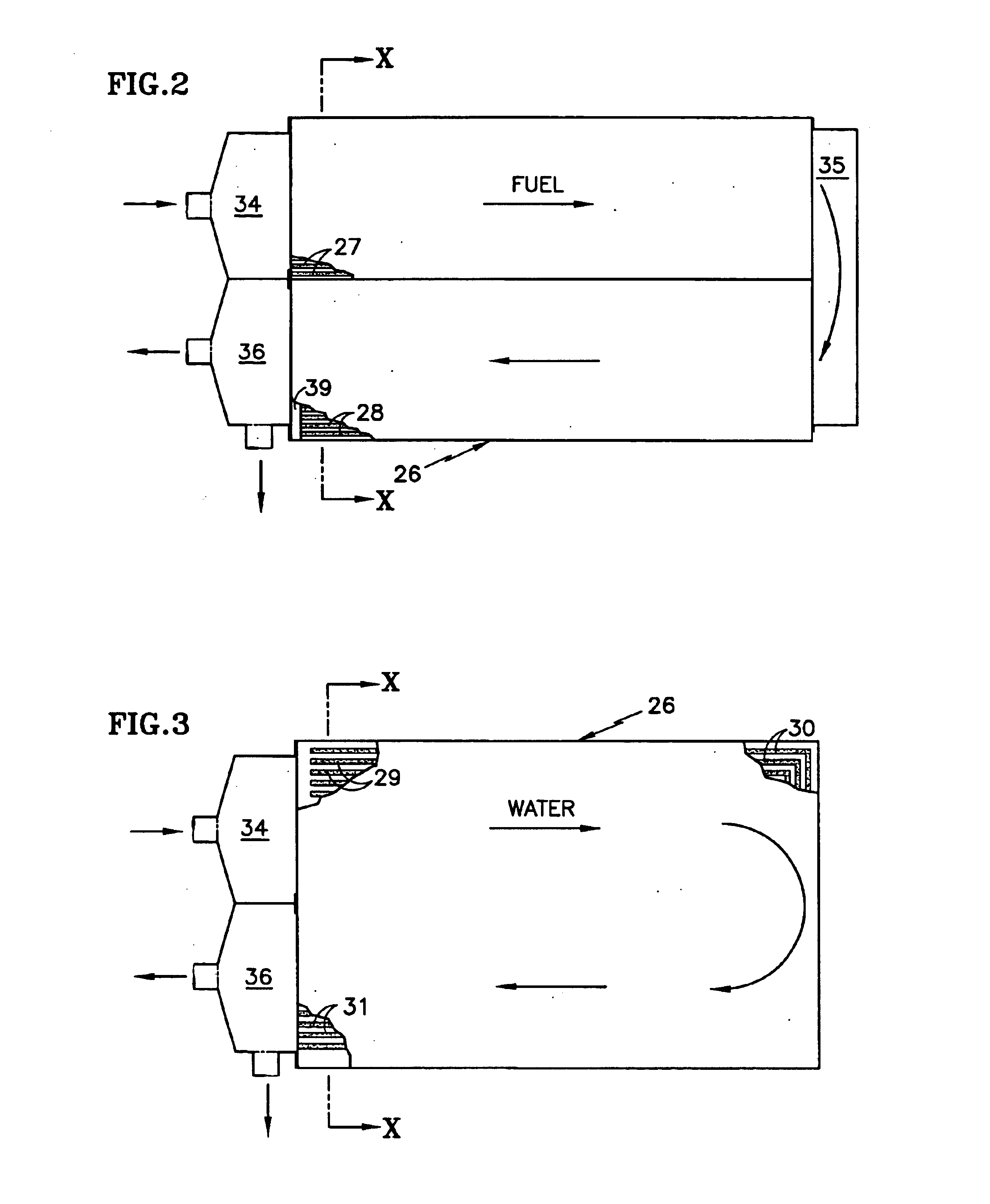
Referring to FIG. 1, a fuel cell stack includes a plurality of fuel cells, each including a PEM 19, an anode substrate 20, with an anode catalyst (not shown) disposed between the membrane 19 and the substrate 20. A cathode catalyst (not shown) extends between the membrane 19 and a cathode substrate 21. A porous anode flow field plate 26 includes fuel reactant gas flow channels 27, 28 on the side thereof adjacent the anode substrate 20 and water flow channels 29-31 on the reverse side thereof. In the exemplary embodiment, as shown in FIG. 2, the fuel flow channels 27 run horizontally from a fuel inlet manifold 34 to a fuel turnaround manifold 35 and the fuel flow channels 28 run from the fuel turnaround manifold 35 to a fuel exit manifold 36. As seen in FIG. 3, the ends 29 of water management channels are dead ended in the region near the fuel inlet manifold 34, and form corners 30 at the opposite end of the fuel flow field plate 26 where they turn toward the other edge of the plate ...


PUM

PropertyMeasurementUnit
pressureaaaaaaaaaa
pressureaaaaaaaaaa
pressureaaaaaaaaaa

Abstract

A proton exchange membrane (PEM) fuel cell includes fuel and oxidant flow field plates (26, 40) having fuel and oxidant channels (27, 28; 41, 44), and water channels, the ends (29, 48) of which that are adjacent to the corresponding reactant gas inlet manifold (34, 42) are dead ended, the other ends (31, 50) draining excess water into the corresponding reactant gas exhaust manifold (36, 45). Flow restrictors (39, 47) maintain reactant gas pressure above exit manifold pressure, and may comprise interdigitated channels (65, 66; 76, 78). Solid reactant gas flow field plates have small holes (85, 88) between reactant gas channels (27, 28; 41) and water drain channels (29, 30; 49, 50). In one embodiment, the fuel cells of a stack may be separated by either coolant plates (51) or solid plates (55) or both. In a second embodiment, coolant plates (51a) have weep holes (57) that inject water into the ends (29) of the reactant gas water channels which are in the region of the inlet manifold (34), thereby assuring humidification of the reactants.

Description

This invention relates to a proton exchange membrane (PEM) fuel cell in which porous reactant gas flow field plates have water flow fields on the reverse sides thereof which are dead-ended near the inlet of the corresponding reactant gas and which drain into the corresponding reactant gas exhaust manifold.Water management in PEM fuel cells includes carrying the product water (resulting from the fuel cell process) and proton drag water (carried through the membrane from the anode side) away from the cathode, while at the same time ensuring that the membrane remains moist, particularly on the anode side. Recent designs of PEM fuel cells employ water transport plates which have reactant gas flow fields on one side and water coolant channels on the other side, to provide both the function of water management and the function of cooling the fuel cells. This requires a balance between promoting the flow of water through the water transport plate to humidify both reactants and to the anode...

Claims


Application Information

Patent Timeline
Patent Type & Authority Patents(United States)
IPC IPC(8): H01M2/00H01M2/02H01M2/08H01M2/14H01M8/02H01M8/10H01M8/04H01M8/24
CPCH01M8/04104H01M8/04134H01M8/04291H01M8/241H01M8/0247Y02E60/50H01M8/0263H01M8/0267H01M8/2457H01M8/2484
Inventor YI, JUNG S.YANG, DELIANGBREAULT, RICHARD D.GRASSO, ALBERT P.SCHEFFLER, GLENN W.
Owner AUDI AG
Why Eureka
Try Eureka