Adjusting device for a multi-beam source unit and image forming apparatus

a multi-beam source unit and image forming technology, applied in lighting and heating apparatus, semiconductor lasers, instruments, etc., can solve the problems of increasing cost and complicated control of the start position of the write position

Inactive Publication Date: 2004-09-28
RICOH KK
View PDF6 Cites 29 Cited by
  • Summary
  • Abstract
  • Description
  • Claims
  • Application Information

AI Technical Summary

Problems solved by technology

In this laser scanning optical system, however, the control it used for aligning write start positions is complicated, with consequent increase of cost.
Even with such a design however, due to errors in the manufacturing process of the multi-beam laser diode 5 being considered, it is rarely the case that the light emitting points 7a-7d are positioned on the virtual straight line Q3 without error.

Method used


Image

  • Adjusting device for a multi-beam source unit and image forming apparatus
  • Adjusting device for a multi-beam source unit and image forming apparatus
  • Adjusting device for a multi-beam source unit and image forming apparatus

Examples


Embodiment Construction

[Multi-beam source unit and method for adjusting the same according to an embodiment of the invention]

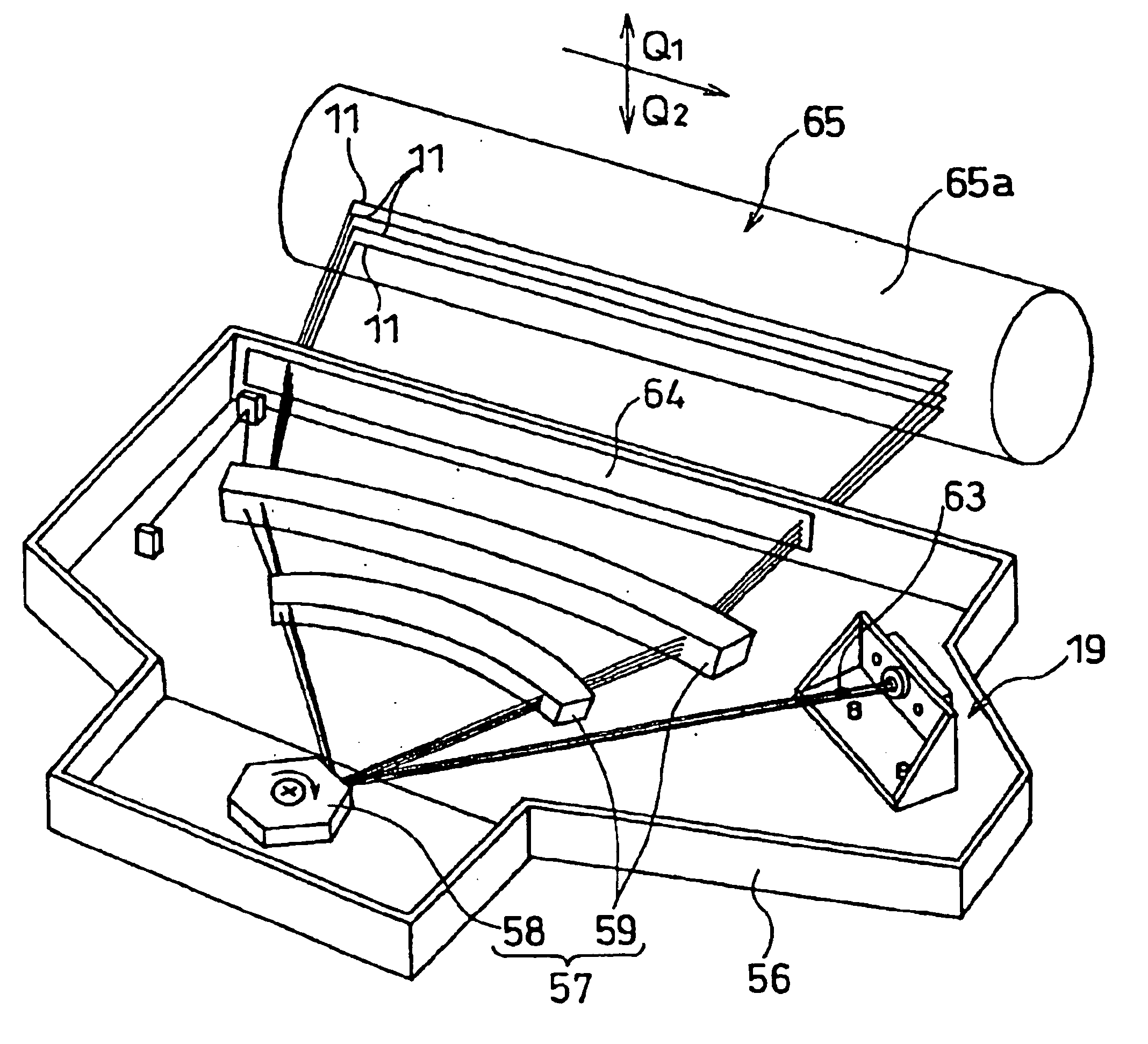
FIG. 7 is an exploded perspective view of a multi-beam source unit 19 embodying the present invention. In the same figure, the reference numeral 20 denotes a mounting bracket. The mounting bracket 20 has a bottom wall portion 21, an upright wall portion 22, and a pair of side wail portions 23. In the bottom wall portion 21 are formed a pair of positioning holes 21a and a pair of screw inserting holes 21b.

On the underside of the bottom wall portion 21 are formed positioning reference portions 24, as shown in FIG. 8. The positioning reference portions 24 are each provided with a horizontal scanning direction reference plane 24a for defining a horizontal scanning direction. The positioning reference portions 24 are to be confronted with positioning reference portions of a housing serving as a body portion of an image forming apparatus which will be described later.

In the upright wall 2...


PUM


Abstract

An adjusting device for a multi-beam source unit includes a mounting bracket, a base member rotatably mounted on the mounting bracket and a multi-beam laser diode provided with light emitting points positioned substantially in a straight line with respect to each other. The multi-beam laser diode is mounted on the base member and radiates a laser beam from the light emitting points. The base member rotates such that the laser beam is radiated onto a predetermined position of an image recording plane of a scanning optical system.

Description

1. Field of the InventionThe present invention relates to a method and device for adjusting a multi-beam source unit used in an image forming apparatus such as a digital copying machine or a laser printer, as well as a method for assembling the multi-beam source unit and an image forming apparatus using the multi-beam source unit.2. Description of the Prior ArtHeretofore, as an image forming apparatus such as a digital copying machine or a laser printer there has been known an image forming apparatus with a laser scanning optic system mounted thereon. With the recent tendency to a higher write accuracy and a higher write speed, a laser scanning optical system using a multi-beam laser diode is becoming most popular.FIG. 1 illustrates such a laser sunning optical system schematically. In the same figure, the reference numeral 1 denotes a multi-beam source unit, numeral 2 denotes a polygon mirror, numeral 3 denotes a f.theta. lens, and numeral 4 denotes a photosensitive member (also ca...

Claims


Application Information

Patent Timeline
Patent Type & Authority Patents(United States)
IPC IPC(8): G02B26/12H01S5/40H01S5/00B41J2/45B41J2/44B41J2/455G02B7/00G02B26/10
CPCG02B26/123H01S5/4025B41J2/473H01S5/005
Inventor OKUWAKI, HIROYUKIKAWAZOE, OSAMUNAOE, YASUHIRO
Owner RICOH KK
Why Eureka
Try Eureka