AGC circuit providing control of output signal amplitude and of output signal DC level
a technology of output signal and output signal, which is applied in the direction of amplifiers with semiconductor devices/discharge tubes, amplifiers with amplification control details, etc., can solve the problem of varying the amplitude of the output signal of the agc circui
- Summary
- Abstract
- Description
- Claims
- Application Information
AI Technical Summary
Problems solved by technology
Method used
Image
Examples
first embodiment
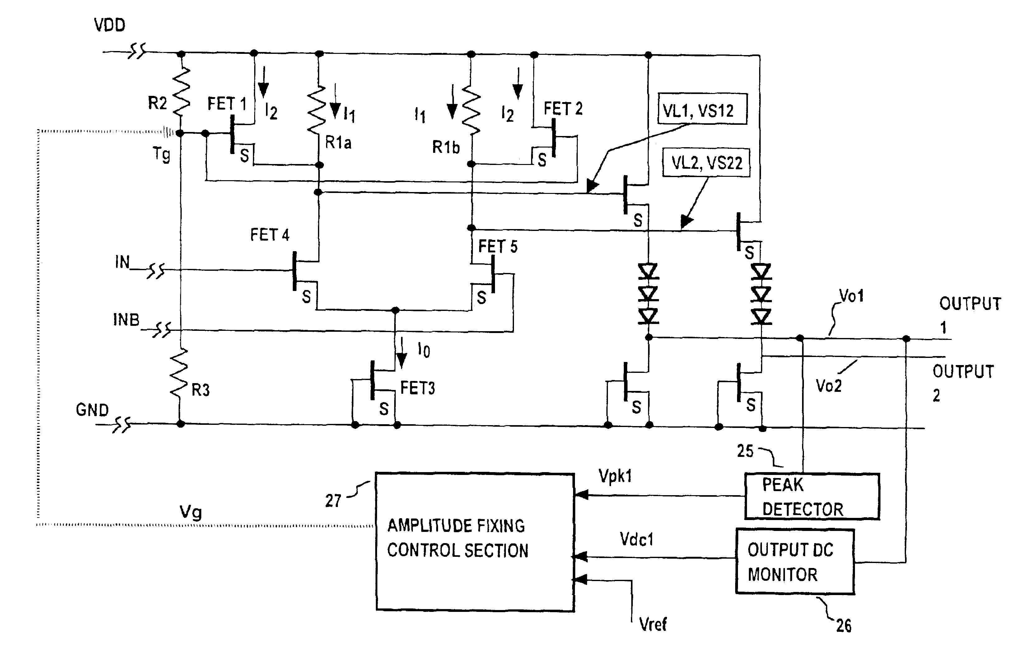
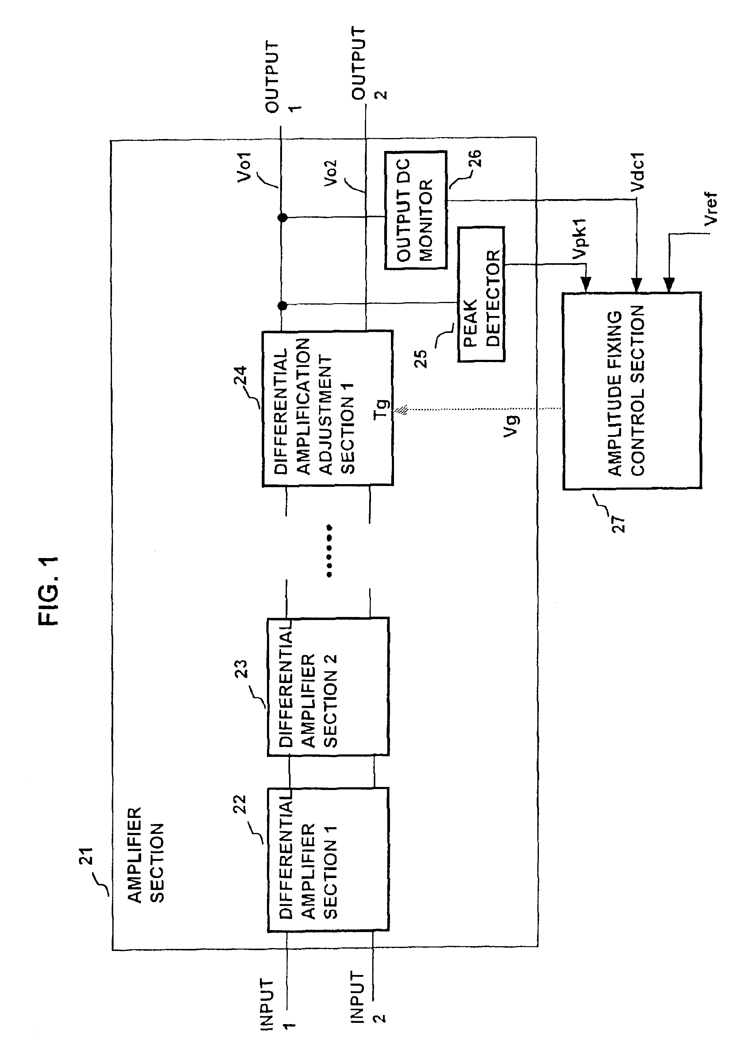
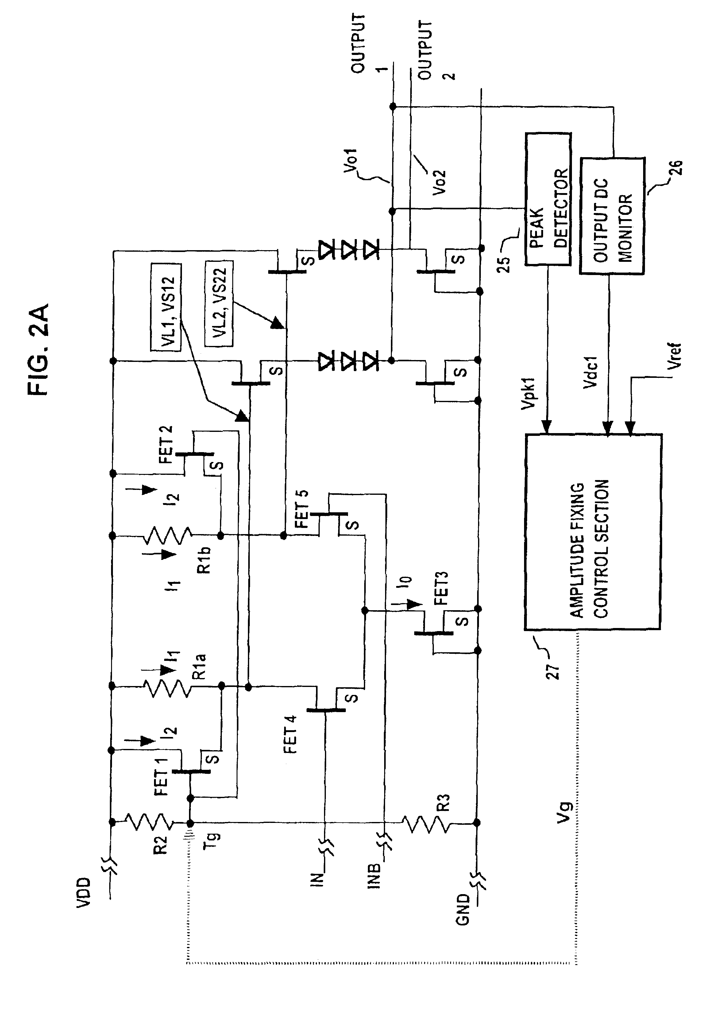
FIG. 1 is a system block diagram showing the overall configuration of a first embodiment of an AGC circuit, while FIGS. 2 to 4 show respective circuits of three examples of the configuration of a differential amplification adjustment circuit section in the first embodiment.
As shown in FIG. 1, the AGC circuit is basically formed of an amplifier section 21 and an amplitude fixing control section 27. The amplifier section 21 includes a plurality of differential amplifier sections 22, 23 etc., connected in series as successive stages, and a differential amplitude adjustment circuit section 24. A pair of input signals of the AGC circuit, designated as Input 1 and Input 2, are supplied to a first stage of the plurality of differential amplifier sections, designated by numeral 22, and a complementary pair of first and second output signals are produced from the final stage and supplied to the differential amplitude adjustment circuit section 24, to be adjusted in amplitude as described her...
second embodiment
FIG. 7 is a general system block diagram of a second embodiment of an AGC circuit, and FIG. 8A shows an example of the circuit configuration of a differential amplification adjustment circuit section of this embodiment and its connection relationships to other system blocks. FIG. 8B shows corresponding signal waveforms.
With the first embodiment, the peak amplitude and DC component values of a specific one of the two controlled output signals Vo1, Vo2 are detected, and their difference is compared with an amplitude control reference voltage to thereby derive an amplitude control signal Vg which is applied to control the amplitude of that specific one of the output signals Vo1, Vo2 to a desired fixed value. With the second embodiment, that control is applied to both of the Vo1, Vo2 signals. In other respects, the operation of the second embodiment is substantially similar to that of the first embodiment.
Specifically, the AGC circuit of FIG. 7 is basically formed of an amplifier sectio...
third embodiment
A third embodiment will be described, referring to the AGC circuit shown in block diagram form in FIG. 10, and to the specific circuit configurations and waveform diagrams of FIGS. 11A, 11B, and 12 to 14. It should be understood that the contents of these diagrams are intended only to illustrate the features and operation of the embodiment, and are not to be understood as limiting the embodiment.
In the following, only features which differ from those of the preceding embodiments are described.
As shown in FIG. 10, this embodiment is formed of an amplifier section 41, an amplitude fixing control section 47, and a voltage control section 141. The amplifier section 41 is formed of a series of cascade-connected differential amplifier sections 42, 43, . . . , with the input signals Input 1, Input 2 being supplied to the first-stage differential amplifier section 42, and the output signals from a final stage of that series of differential amplifier sections being supplied to a differential...
PUM
 Abstract
Description
Claims
Application Information
 - R&D
- Intellectual Property
- Life Sciences
- Materials
- Tech Scout
- Unparalleled Data Quality
- Higher Quality Content
- 60% Fewer Hallucinations
Browse by: Latest US Patents, China's latest patents, Technical Efficacy Thesaurus, Application Domain, Technology Topic, Popular Technical Reports.
© 2025 PatSnap. All rights reserved.Legal|Privacy policy|Modern Slavery Act Transparency Statement|Sitemap|About US| Contact US: help@patsnap.com


