Fuel injection timing control apparatus and control method thereof for in-cylinder injection gasoline engine

a timing control apparatus and fuel injection technology, which is applied in mechanical equipment, electric control, machines/engines, etc., can solve the problems of deterioration of exhaust gas emissions, difficult to completely prevent the adherence of fuel to the piston top face, and large amount of injected fuel to adhere, so as to reduce the rate at which fuel is injected and reduce the amount of fuel that reaches the cylinder inner peripheral face. , the effect of fuel adhesion

Inactive Publication Date: 2004-11-02
TOYOTA JIDOSHA KK
View PDF3 Cites 17 Cited by
  • Summary
  • Abstract
  • Description
  • Claims
  • Application Information

AI Technical Summary

Benefits of technology

According to this construction, when the degree of fuel dilution of the overall lubricating oil is small, for example, it is possible to give priority to suppressing the adhesion of fuel on the piston top face in order to inhibit, to as great an extent as possible, deterioration of the exhaust gas emissions, such as the generation of black smoke, and temporarily allow a fuel injection even if that fuel injection would increase the amount of fuel adhered to the cylinder inner peripheral face and cause the fuel dilution to progress. In contrast, when the degree of fuel dilution of the overall lubricating oil increases to the point where, if it progresses any farther the resultant adverse effects, such as a decline in lubricating performance, can no longer be ignored, the fuel injection mode is controlled so as to inhibit dilution by fuel of the lubricating oil. As a result, it is possible to inhibit adverse effects from the fuel dilution of the lubricating oil on the internal combustion engine.
Therefore, it is possible to accurately estimate the degree of fuel dilution together with the increase in the degree of fuel dilution by sequentially updating the value of the current degree of fuel dilution based on the calculated rate of increase and learning the updated value of the degree of fuel dilution as the value of the new degree of fuel dilution.

Problems solved by technology

In this in-cylinder injection internal combustion engine, however, the following problems may occur, particularly when the engine is cold, when the fuel is directly injected into the cylinder.
That is, when the engine is cold, fuel within the cylinder does not readily atomize, resulting in a tendency for a large amount of the injected fuel to adhere to the top face of an engine piston (hereinafter referred to simply as "piston top face") and the cylinder inner peripheral face.
Even if this intake stroke injection is performed, however, it is still difficult to completely prevent the adherence of fuel on the piston top face and cylinder inner peripheral face; some of the injected fuel is not burned, but remains adhered after engine combustion.
The fuel adhered to the piston top face, in particular, atomizes gradually during later engine combustion, and is discharged from the cylinder without being completely combusted, leading to a deterioration of exhaust gas emissions, such as the generation of black smoke and an increase in unburned components.
Therefore, if fuel dilution of the lubricating oil occurs frequently, the ratio of fuel mixed in with the overall lubricating oil gradually increases until finally adverse effects result, such as a decline in the lubricating performance in the internal combustion engine.
Further, the fuel contained in the lubricating oil decreases by gradually evaporating over time.
On the other hand, deterioration of the exhaust gas emissions due to fuel adhered to the piston top face is to a great extent unavoidable, and the allowable range in consideration of the degree of the adverse effects on the internal combustion engine is extremely narrow.

Method used


Image

  • Fuel injection timing control apparatus and control method thereof for in-cylinder injection gasoline engine
  • Fuel injection timing control apparatus and control method thereof for in-cylinder injection gasoline engine
  • Fuel injection timing control apparatus and control method thereof for in-cylinder injection gasoline engine

Examples


Embodiment Construction

Hereinafter, a first exemplary embodiment according to the invention will be described.

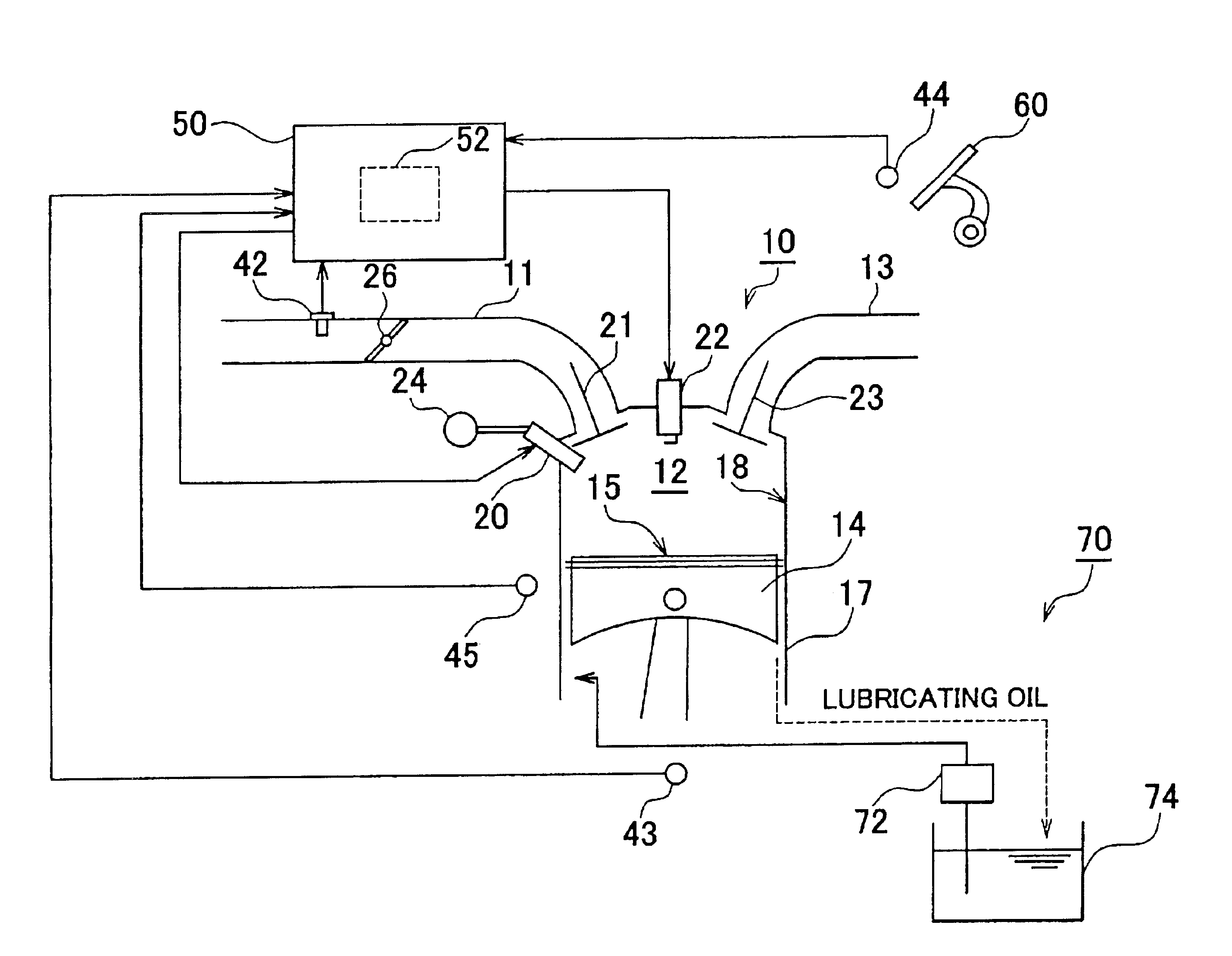
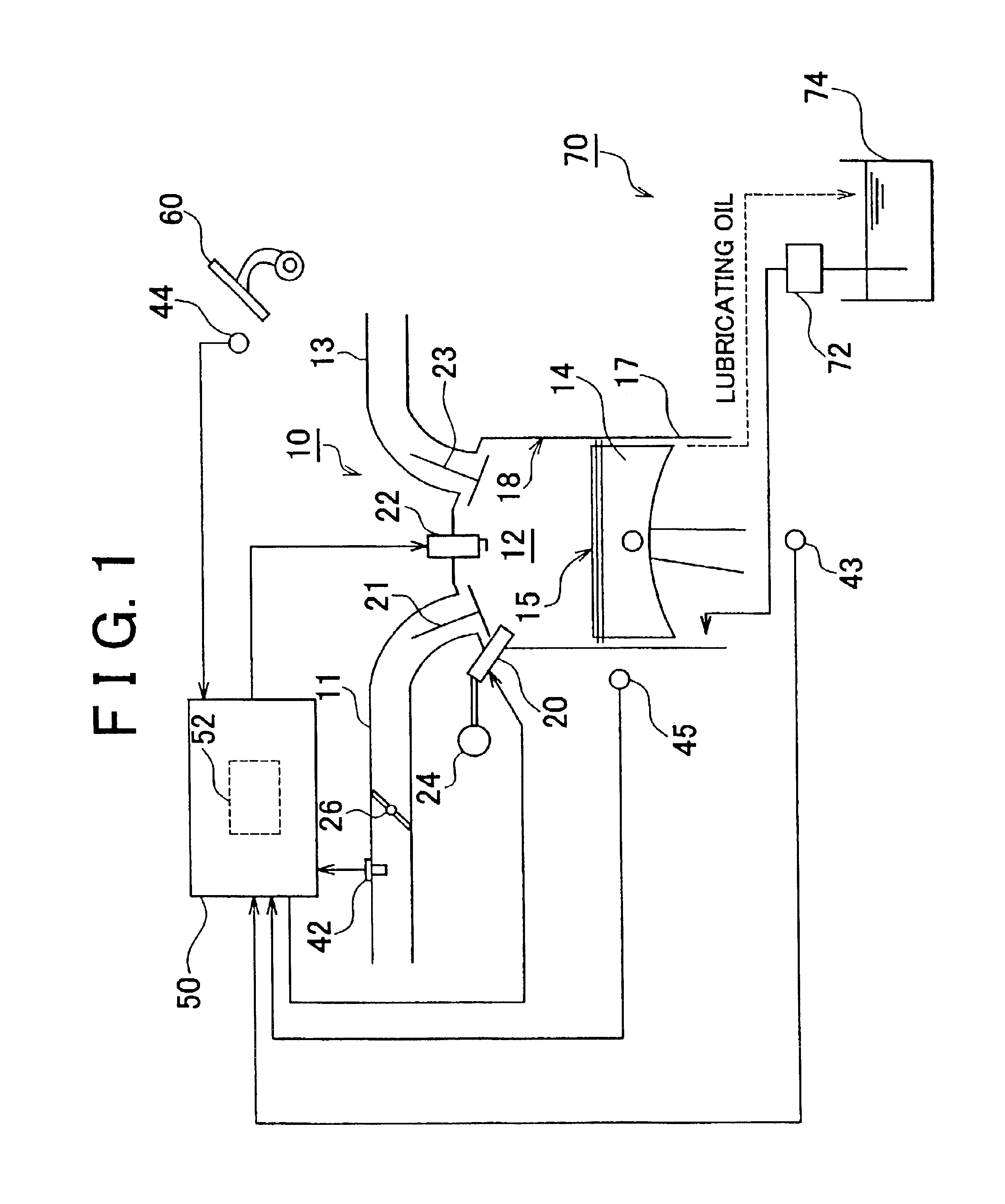
FIG. 1 is a schematic diagram of a fuel injection control apparatus according to this exemplary embodiment, showing an internal combustion engine 10 to which this fuel injection control apparatus has been applied, and a lubrication system 70 that supplies lubricating oil to the internal combustion engine 10.

As shown in FIG. 1, the internal combustion engine 10 is an in-cylinder injection type internal combustion engine in which fuel is injected directly into a combustion chamber 12 of each cylinder 17 from a fuel injection valve 20. An engine piston (hereinafter simply referred to as "piston") 14 is provided within each cylinder 17 so as to be able to move in a reciprocating motion. The combustion chamber 12 is defined by a piston top face 15 of this piston 14, and a cylinder inner peripheral face 18.

An intake passage 11 and an exhaust passage 13 are both connected to this combustion chamber 12. M...


PUM


Abstract

A fuel injection mode is flexibly controlled according to the actual extent of adverse effects on an internal combustion engine from both deterioration of exhaust gas emissions and fuel dilution caused by fuel adhering to the piston top face and the cylinder inner peripheral face. A dilution degree counter value C is counted up when a coolant temperature at engine startup THWST and an intake air quantity sum value after engine startup GASUM are each equal to, or less than, respective predetermined values. A fuel dilution flag is set to "ON" when the dilution degree counter value C is equal to, or greater than, a predetermined value CH. A fuel injection timing of an intake stroke injection is changed to a timing on the advance side when this fuel dilution flag is "ON."

Description

INCORPORATION BY REFERENCEThe disclosure of Japanese Patent Application No. 2002-163578 filed on Apr. 26, 2002, including the specification, drawings and abstract is incorporated herein by reference in its entirety.BACKGROUND OF THE INVENTION1. Field of the InventionThis invention relates to a fuel injection timing control apparatus for an in-cylinder injection internal combustion engine, which controls a fuel injection in an in-cylinder injection internal combustion engine in which fuel is directly injected into a cylinder.2. Description of the Related ArtIn the past, an in-cylinder injection internal combustion engine in which fuel is directly injected into a cylinder of the internal combustion engine has been proposed. This in-cylinder injection internal combustion engine aims to improve fuel economy and the like by precisely controlling the mixture state of a mixture within the cylinder by injecting fuel late in the compression stroke. In this in-cylinder injection internal comb...

Claims


Application Information

Patent Timeline
Patent Type & Authority Patents(United States)
IPC IPC(8): F02D41/06F02D41/04F02D41/40F02D41/30F02D45/00F02D41/02F02D41/24F02D41/34
CPCF02D41/047F02D41/061F02D41/3076F02D41/401F02D41/3029F02D41/06F02D41/064F02D41/2451Y02T10/44F02D2041/1433F02D2041/389F02D2250/11Y02T10/40
Inventor ITO, YUKIKAZUHIROSE, KIYOOHONDA, KOJI
Owner TOYOTA JIDOSHA KK
Why Eureka
Try Eureka