Control system for an electronic sign (video display system)

a control system and electronic sign technology, applied in the direction of identification means, instruments, static indicating devices, etc., can solve the problems of not providing sharply defined images, prior art display sign control systems are technology dependent, and prior art sign control systems cannot accommodate different sizes of signs

Inactive Publication Date: 2004-11-16
DAKTRONICS
View PDF11 Cites 58 Cited by
  • Summary
  • Abstract
  • Description
  • Claims
  • Application Information

AI Technical Summary

Benefits of technology

We have no configuration switches in our signs (auto configurable). The dual line controller provides great flexibility for manufacturing and for long term maintenance for the customer.
Module calibration and pixel to pixel calibration information is stored on each RGB LED driver board. When the system powers up, the dual line controller retrieves the calibration information from the module and stores it. This information is used to help the dual line controller drive the modules in a way that gives the display a nice consistent appearance. The dual line controller can receive an additional module intensity offset from the VMAX3 system to allow the operator some adjustment on a module by module basis.

Problems solved by technology

Prior art display sign control systems have been technology dependent and have not provided sharply defined images when combining animation or other signals developed in a character generator and video.
The problem arises when the sign control system attempts to fit the digitized version of the original analog character generator signal into the pixel matrix elements of the sign.
Further, prior art sign control systems did not accommodate different sizes of signs, but were generally limited to a specific size and / or type of sign.
The prior art systems did not always provide for the combination of live video, graphics, animation, real time data, information such as sports statistics, text information, or such features as instant replay.

Method used


Image

  • Control system for an electronic sign (video display system)
  • Control system for an electronic sign (video display system)
  • Control system for an electronic sign (video display system)

Examples


Embodiment Construction

Venus.RTM. 7000 Sign Service Operational Description

1. General Overview

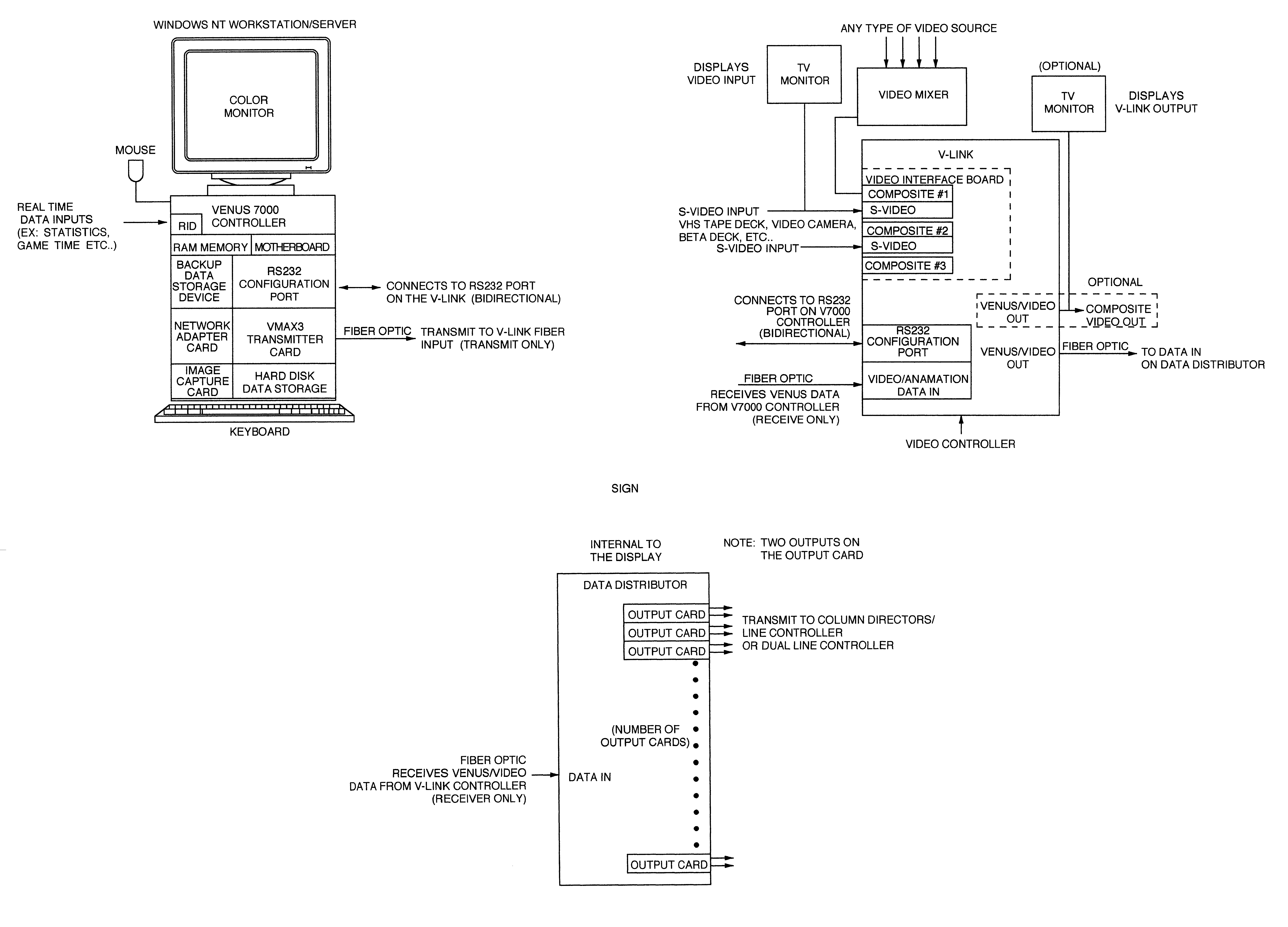
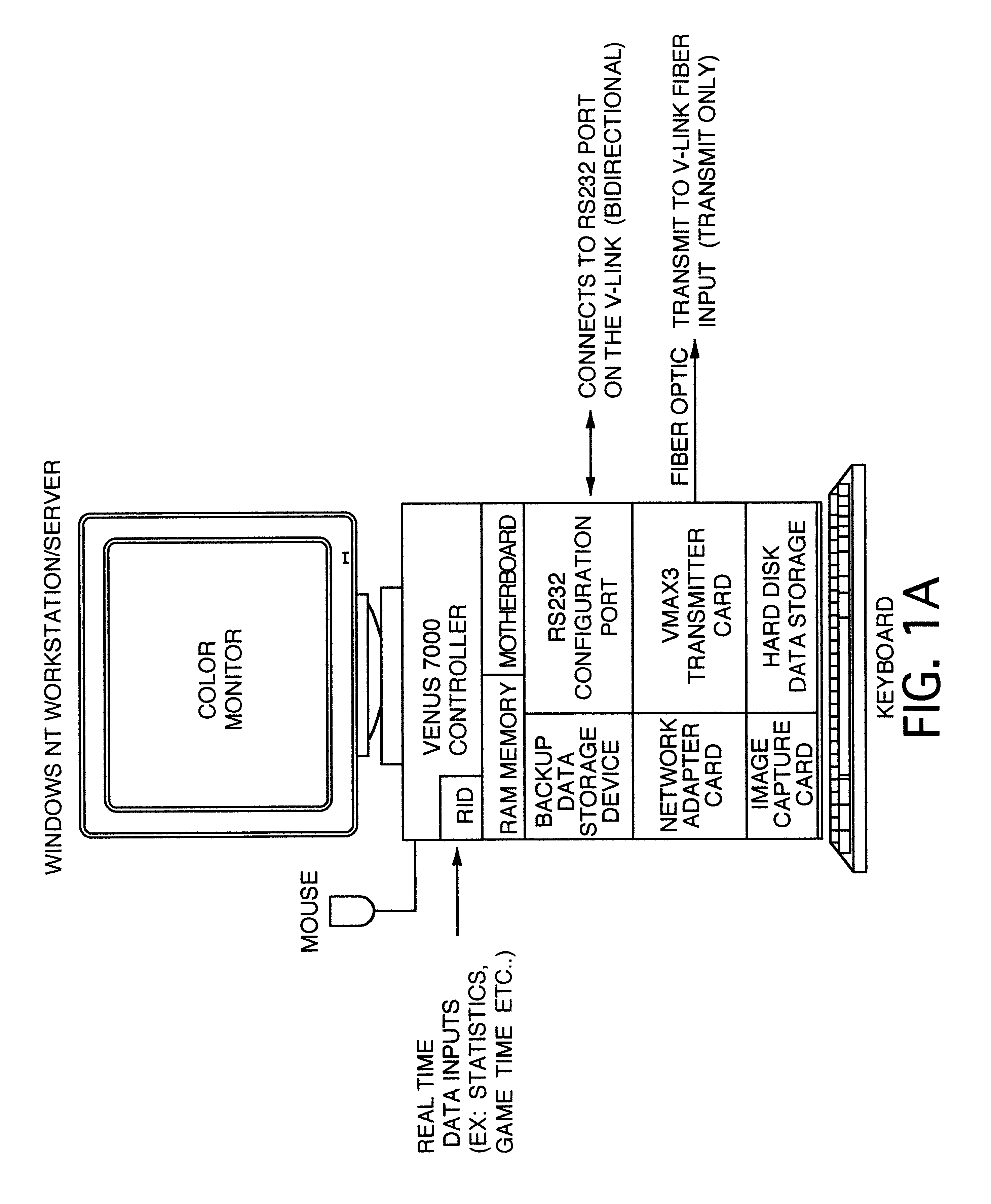
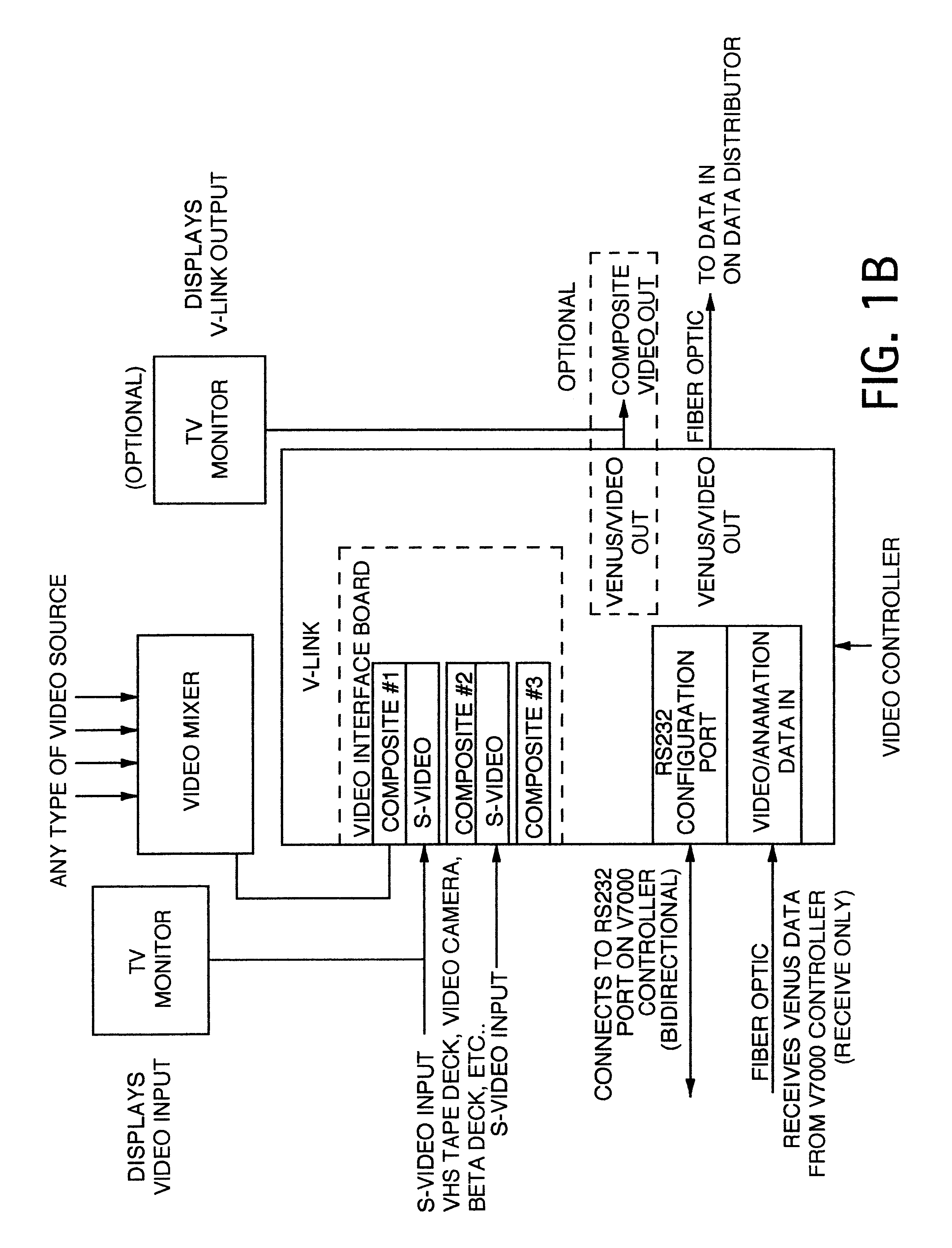
The Venus.RTM. series controllers of FIGS. 24 and 25 are used to operation the large matrix displays produced by Daktronics, Inc. This family has migrated across several platforms an operating systems during the 15 years of its lifetime.

These controllers generally have four (4) major functions: create images for display, schedule the images for display, interface to external data sources, and send the image data to the display.

The Venus.RTM. 7000 controller is the most recent member of the Venus.RTM. family and is based on the Windows.RTM. NT operating system running on Intel based processor systems. It provides all of the functions of earlier Venus.RTM. controllers and extends the capabilities to support larger, video-type displays.

This document will describe the basic operations of the Venus.RTM. 7000 Sign Service. This module of the controller is responsible to receive display control information from other mo...


PUM


Abstract

A video display system including an electronic sign, a electronic sign control system utilizing a general purpose personal computer, having a video interface card, controlled by clock and command signals from said personal computer, containing a plurality of video and digital input ports and a high speed output port, a transmitter link control card, also under the control of clock and command signals from said personal computer, for transmitting video display, clock, and command signals to a remote data receiver and distributor associated with the electronic sign, which converts said signals into device control signals for controlling individual sign display elements.

Description

CROSS REFERENCES TO CO-PENDING APPLICATIONSNone.1. Field of the InventionThis invention relates to a remote control system for an electrically controlled sign. The system accepts input data in analog video, digital video, digital or similar forms, converts it to sign and control signals, and transmits the converted signal2. Description of the Prior ArtPrior art display sign control systems have been technology dependent and have not provided sharply defined images when combining animation or other signals developed in a character generator and video. The problem arises when the sign control system attempts to fit the digitized version of the original analog character generator signal into the pixel matrix elements of the sign. Since there is not an exact match between the digitized version and the available pixels, the resulting output signal to the individual pixels varies from the optimum representation. The resulting display provided images in which the character generator output...

Claims


Application Information

Patent Timeline
Patent Type & Authority Patents(United States)
IPC IPC(8): G09F9/33
CPCG09F9/33G09F9/3026G09F27/008Y10S345/903
Inventor BERGER, BRENT HENRYKURTENBACH, REECE ALANSCHULTE, DANIEL ANTHONYSCHULTE, JOSEPH GERARDWENDLER, BRETT DAVID
Owner DAKTRONICS
Why Eureka
Try Eureka