
Method of manufacturing honeycomb structures

a technology of honeycomb and manufacturing method, which is applied in the direction of manufacturing tools, buttons, paper/cardboard articles, etc., can solve the problems of not only affecting the overall appearance, but also the structure is damaged, and the operation is very awkward, so as to eliminate the roughness

Inactive Publication Date: 2004-12-14
SNECMA MOTEURS SA
View PDF10 Cites 15 Cited by
  • Summary
  • Abstract
  • Description
  • Claims
  • Application Information

AI Technical Summary

Benefits of technology

"The present invention provides a method for manufacturing a honeycomb structure by forming staggered cells through the entire thickness of a fiber fabric, causing pegs to penetrate into the cells, expanding the pegs to fill the cells and exert pressure on the inside faces of the cells, and then shrinking and withdrawing the pegs. The method also includes steps of applying a backing plate to hold the fiber fabric against the pegs, impregnating the fiber fabric with resin to hold the cells open, and curing the resin. Tooling is also provided for implementing the method. The technical effects of the invention include reducing roughness on the inside faces of the cells, conferring a regular shape thereto, and eliminating the need for multiple steps in the manufacturing process."

Problems solved by technology

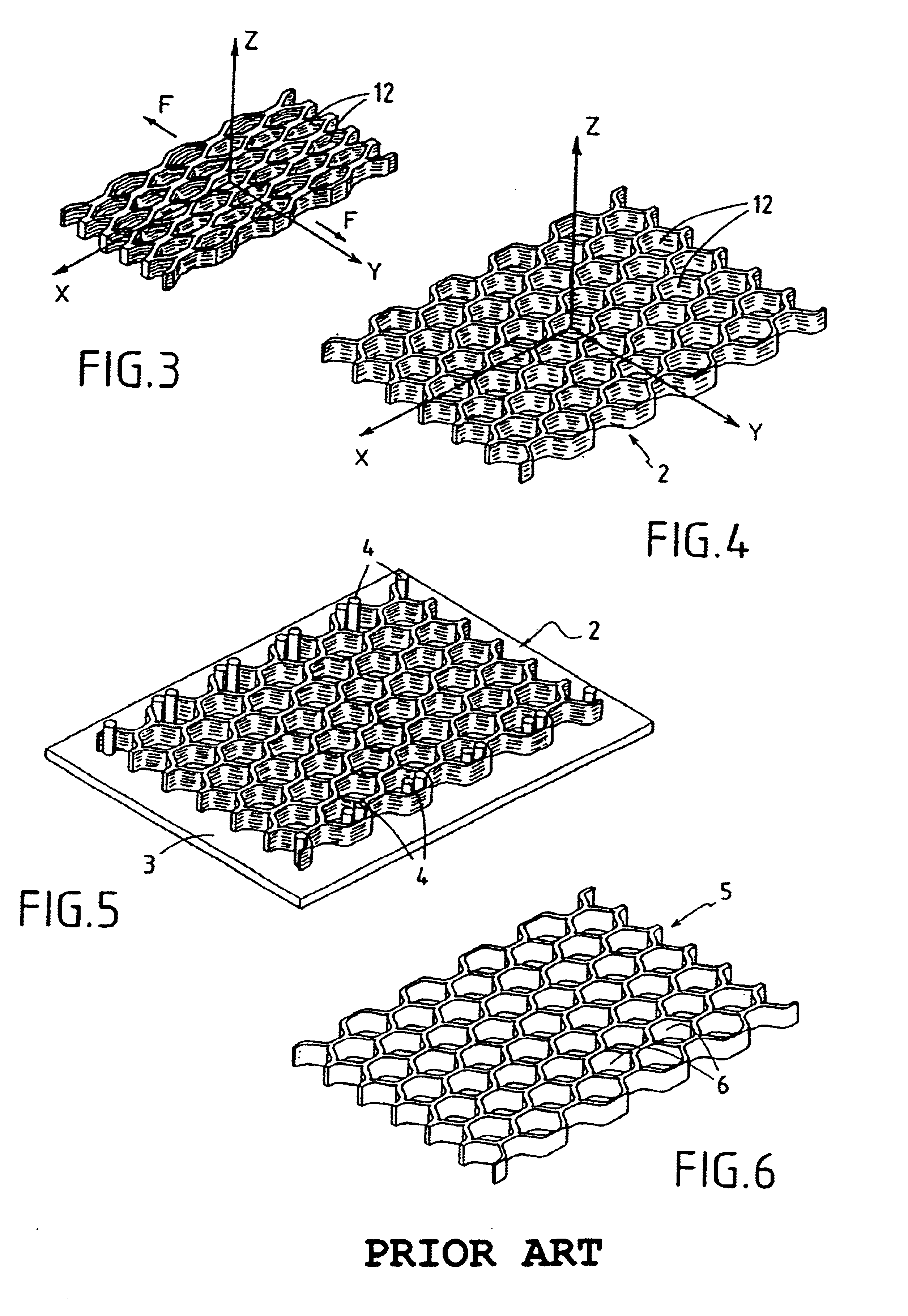
In practice, it has been found that the inside faces of the cells obtained in this way (cf. reference 6 in FIG. 6) are not perfectly smooth, and often present surface defects such as roughness which can lead to injury while the structure is being handled.
Nevertheless such an operation is very awkward.
Another drawback of the above-mentioned method lies in the fact that the cells in the final product are not always entirely regular in shape, i.e. in particular the cells are not all of the same shape, which is not only harmful to overall appearance, but can also reduce the strength of the structure.

Method used


Image

  • Method of manufacturing honeycomb structures
  • Method of manufacturing honeycomb structures
  • Method of manufacturing honeycomb structures

Examples


first embodiment

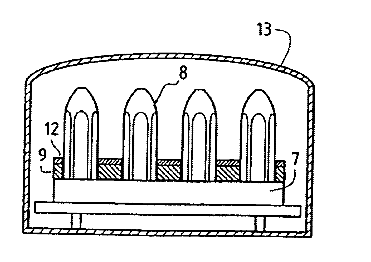
This special tooling comprises, in a first embodiment, a metal support plate 7 and pegs 8 projecting upwards from the support plate 7 (cf. FIG. 7). There are at least as many pegs 8 as there are cells (where the cells are referenced 90) in the deployed fabric 9, and the pegs are mounted on the support plate 7 in positions which correspond to the positions of the cells 90.

With reference to FIG. 8, the end of each peg 8 in contact with the support plate 7 is fixed to said plate by screw fastening, in particular by means of a threaded rod 10 attached to the peg 8. The threaded rod 10 has a first portion 100 received inside the peg and a second portion 101 projecting from the proximal end face of the peg. The projecting portion 101 of each threaded rod 10 passes through a corresponding bore 70 in the support plate 7 and its free end receives a nut 11 serving to hold the peg 8 against the top face of the support plate 7.

The bores 70 are preferably of diameter greater than the diameter of...

second embodiment

FIGS. 13 and 14 show the tooling of the invention.

In this second embodiment, the tooling comprises a support plate 14 and pegs in the form of inflatable bladders 15 fixed via bases 16 to the support plate 14. The bases 16 are preferably held slightly loosely to the support plate 14 so that the pegs 15 can move sufficiently relative to the plate, as in the first embodiment.

The inflatable bladders 15 are made of polyurethane, for example. The inside of each inflatable bladder 15 communicates with a pressurized gas generator 17 via the following in succession: an orifice provided through the corresponding base 16; an orifice 140 in the support plate 14; and a duct 18. Valves 20 (shown diagrammatically in FIG. 13), such as check valves controlled by the pressure in the bladders 15, and pressure limiters 21 of the controlled valve type are also provided in the orifices 140 and in the ducts 18, respectively.

The tooling 14, 15, 16 is used in a manner substantially comparable to the tooling...


PUM

PropertyMeasurementUnit
thicknessaaaaaaaaaa
sizeaaaaaaaaaa
pressureaaaaaaaaaa

Abstract

A method of manufacturing a honeycomb structure, the method comprising the steps of forming staggered cells through the entire thickness of a fiber fabric, causing loosely held pegs to penetrate into respective ones of the cells, each peg having a cross-section of size smaller than that of the corresponding cell and being made of a material that is suitable for expanding; expanding the pegs so that they fill the cells and exert pressure on the inside faces of the cells; and shrinking the pegs and then withdrawing them.

Description

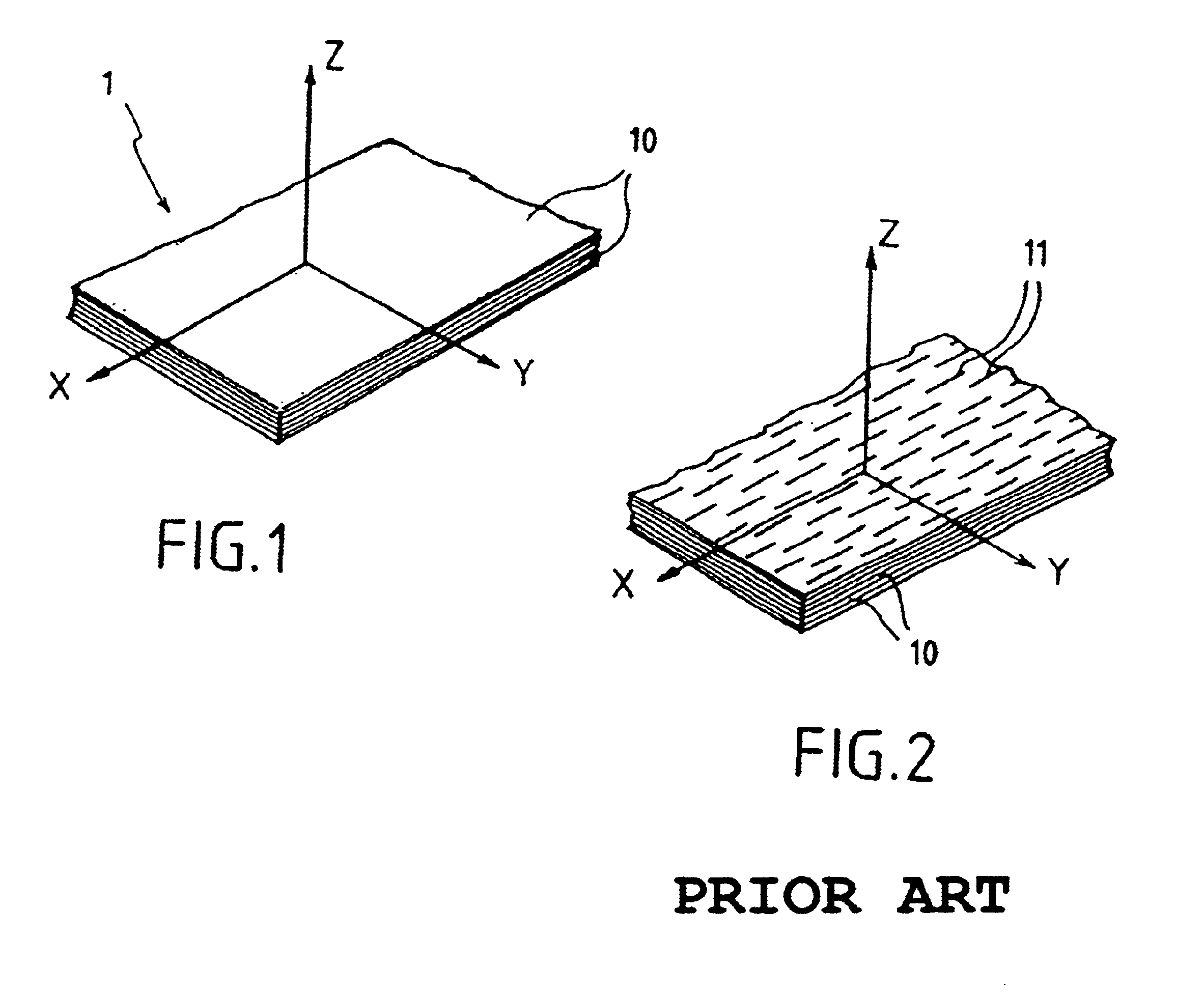
The present invention relates to manufacturing honeycomb structures, and more particularly honeycomb structures made of composite material. The invention also relates to tooling suitable for this purpose.Honeycomb structures, in particular those made of composite material, are advantageous in that they generally present good mechanical properties, while being light in weight. They can be used, for example, as furnace bottoms.DESCRIPTION OF THE PRIOR ARTSeveral methods exist for manufacturing honeycomb structures out of composite material.One such method is shown in FIGS. 1 to 6 and comprises a three-dimensional reinforcing fabric of carbon fibers 1 which is prepared by stacking carbon fiber plies 10 and binding them together by needling, stitching, or any other analogous technique (FIG. 1).Cuts 11 in the form of parallel slits placed in a staggered configuration are made through the fiber fabric 1 perpendicularly to the XY planes of the plies 10, e.g. by means of a knife or by using...

Claims


Application Information

Patent Timeline
Patent Type & Authority Patents(United States)
IPC IPC(8): B29D31/00B29D99/00
CPCB29D99/0089Y10T156/1003Y10T156/1052Y10T29/49906Y10T156/1026Y10T29/5343Y10T29/4998
Inventor MAUMUS, JEAN PIERREGRONDIN, CLAUDE
Owner SNECMA MOTEURS SA
Learn More