Method for adjusting a head suspension parameter

a technology of head suspension and parameter, which is applied in the direction of laser beam welding apparatus, manufacturing tools, shaping tools, etc., can solve the problems of rolling bias in the static attitude of the head suspension

Inactive Publication Date: 2005-01-04
HUTCHINSON TECH
View PDF43 Cites 19 Cited by
  • Summary
  • Abstract
  • Description
  • Claims
  • Application Information

AI Technical Summary

Benefits of technology

In a second embodiment, a first scan region can be located on a cross piece of a head suspension flexure. The first scan region is spaced apart from the longitudinal axis of the head suspension in a first direction, and a second scan region can be located on the cross piece of the flexure spaced apart from the longitudinal axis in a second direction opposite from the first direction. A plurality of lines can be scanned in each of the first and second scan regions, with the plurality of lines being spaced apart from each other and parallel to the longitudinal axis of the head suspension. The plurality of lines will cause the cross piece to warp in the scan region, which will twist the flexure and cause a roll bias in the static attitude of the head suspension. In such an embodiment scan regions can also be located on the spring arms of the flexure, with a plurality of lines scanned in the spring arm scan regions to effect a pitch bias in the static attitude.

Problems solved by technology

The plurality of lines will cause the cross piece to warp in the scan region, which will twist the flexure and cause a roll bias in the static attitude of the head suspension.

Method used


Image

  • Method for adjusting a head suspension parameter
  • Method for adjusting a head suspension parameter
  • Method for adjusting a head suspension parameter

Examples


Embodiment Construction

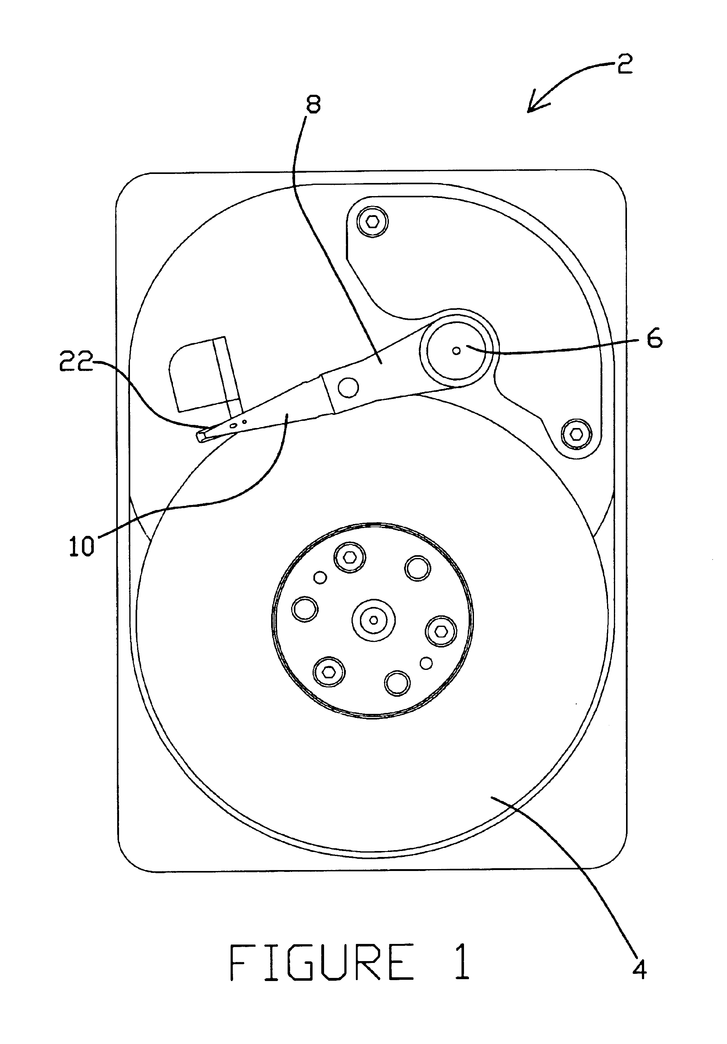
With reference now to the Figures, a disk drive 2 having a head suspension 10 suspended over a disk 4 is shown in FIG. 1. Head suspension 10 supports a head slider 22 at its distal end over the disk 4. Head suspension 10 is attached at its proximal end to an actuator arm 8, which is coupled to an actuator motor 6 mounted within disk drive 2. Actuator motor 6 is used to position the actuator arm 8, head suspension 10, and slider 22 over a desired position on the disk 4. In the embodiment shown, actuator motor 6 is rotary in nature, and operates to radially position the head suspension 10 and slider 22 over disk 4. Other actuator motors, such as a linear actuator motor, can of course be used.

In use, head slider 22 reads and / or writes data to and from disk 4 in disk drive 2, and the head suspension 10 supports and aligns the head slider 22 over a desired location on disk 4 in response to signals received from a microprocessor (not shown). Disk 4 rapidly spins about an axis, and an air ...


PUM

PropertyMeasurementUnit
heightsaaaaaaaaaa
poweraaaaaaaaaa
poweraaaaaaaaaa

Abstract

A method for adjusting the static attitude of a head suspension by scanning a region of the head suspension with a laser. A head suspension having a gimbal region is provided that permits a head slider attached thereto to gimbal about pitch and roll axes in response to fluctuations in an air bearing over which the head slider flies. One or more predetermined regions of the head suspension are irradiated by a laser beam by scanning the laser beam across the head suspension regions to affect the static attitude of the head suspension. In a preferred embodiment, a plurality of parallel spaced apart lines are scanned on the leaf spring arms of a flexure with the laser to correct pitch errors in static attitude, and a plurality of parallel spaced apart lines are scanned with the laser in the cross section attached to the leaf spring arms to correct roll errors in static attitude. One or both sides of the head suspension can be scanned to create a desired pitch and/or roll correction. In addition, the predetermined scan regions can be scanned with a second plurality of lines to provide a precise static attitude adjustment.

Description

TECHNICAL FIELDThe present invention relates generally to a method for adjusting a parameter of a head suspension through the application of heat to the head suspension. In particular, the present invention is a method for adjusting the static attitude of a head suspension by scanning with a laser beam a plurality of lines in a desired region of the head suspension.BACKGROUND OF THE INVENTIONHead suspensions are well known and commonly used within dynamic magnetic or optical information storage devices or drives with rigid disks. The head suspension is a component within the disk drive that positions a magnetic or optical read / write head over a desired position on the storage media where information is to be retrieved (read) or transferred (written). Head suspensions for use in rigid disk drives typically include a load beam that generates a spring force and that supports a flexure to which a head slider having a read / write head is to be mounted. The load beam includes a mounting re...

Claims


Application Information

Patent Timeline
Patent Type & Authority Patents(United States)
IPC IPC(8): B21D37/00B21D37/16G11B5/48
CPCG11B5/4826G11B5/4833Y10T29/49036
Inventor UBL, TIMOTHY RAYMONDBALASUBRAMANIAM, SENTHILKOBA, HRYHORY T.
Owner HUTCHINSON TECH
Why Eureka
Try Eureka