Material thickness measurement method and apparatus

a technology of thickness measurement and material, applied in the field of methods and equipment, can solve the problems of material surface significantly dropping, measurement accuracy deteriorating, and total measuring system becoming complex and expensive, and achieve the effect of simple system configuration and high accuracy

Inactive Publication Date: 2005-01-04
OPTECH VENTURES
View PDF5 Cites 25 Cited by
  • Summary
  • Abstract
  • Description
  • Claims
  • Application Information

AI Technical Summary

Benefits of technology

An object of this invention is to address the above-mentioned problems, and to provide a material thickness measurement method and apparatus which can be applied to a non-conductive material and measure a material thickness with a simple system configuration, with high accuracy and in a non-contact manner, even in a measurement environment in which the material wobbles and the material temperature significantly changes.

Problems solved by technology

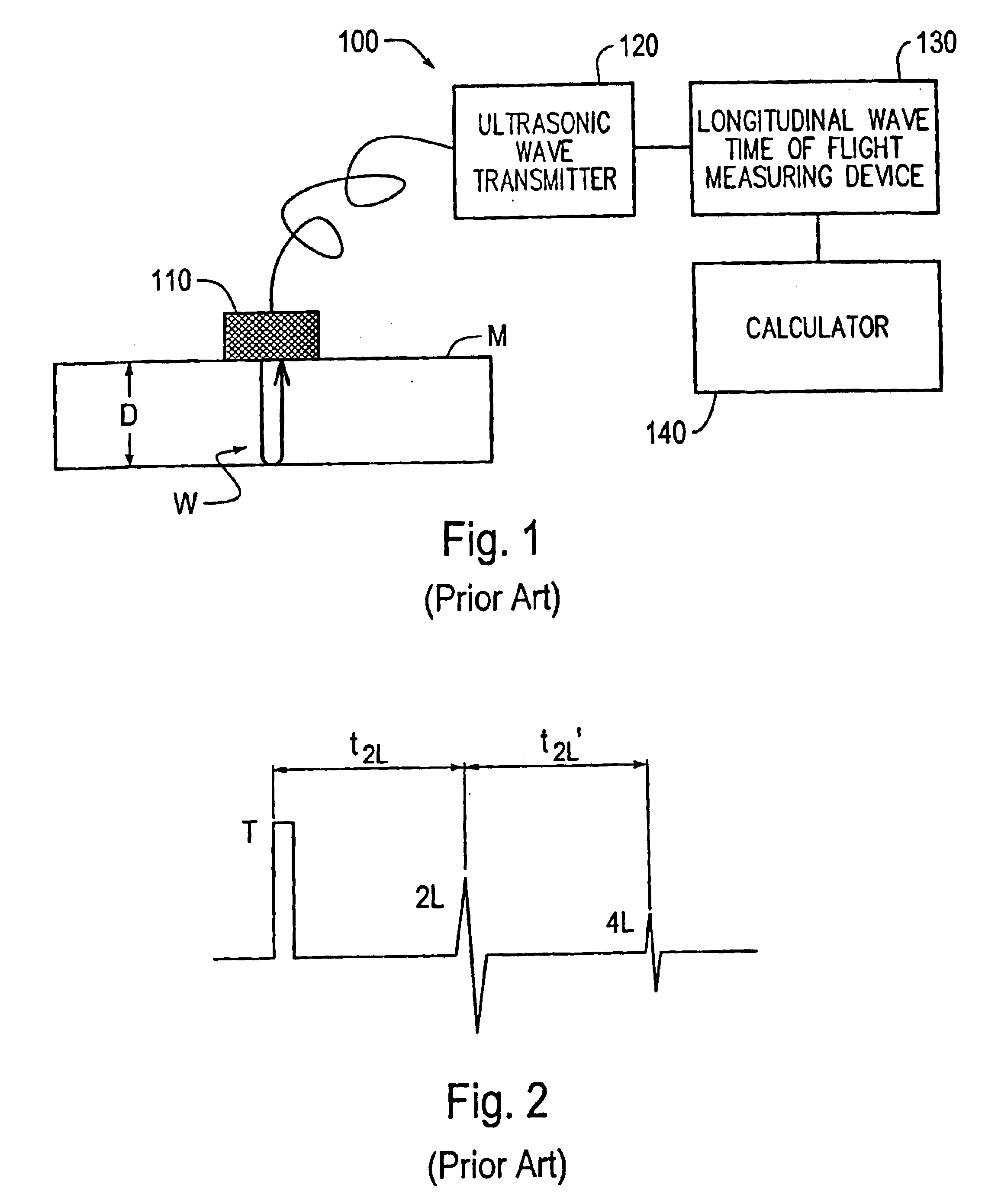
However, in the material thickness measurement method using the laser ultrasonic technique and the pyrometer, (1) there is a need for separately providing a highly accurate pyrometer in order to measure thickness, and the total measuring system becomes complex and expensive, and (2) with a pyrometer, only the material surface temperature can be measured.
Meanwhile, ultrasonic wave velocity changes depending on the internal temperature of the material, so when the material surface temperature cannot be considered to be the same as the internal temperature, the measurement accuracy deteriorates.
For example, when the material thickness is relatively thick and the material has a high temperature, the temperature of the material surface significantly drops due to heat radiation, compared to the inside of the material, so the latter problem is quite significant.
Furthermore, in the above-mentioned thickness measurement method using the electromagnetic acoustic transducers, (1) in principle, this can be only applied to conductive materials, (2) the measuring head is complicated and large because of necessity for an incorporation of both a longitudinal wave transducer and a shear wave transducer, and (3) the standoff distance between the electromagnetic acoustic transducer and the material surface needs to be extremely small (e.g., 1 mm), so it is difficult to apply to a manufacturing line in which a material moves while wobbling up and down, or to a manufacturing line or the like which processes materials of various thickness values.

Method used


Image

  • Material thickness measurement method and apparatus
  • Material thickness measurement method and apparatus
  • Material thickness measurement method and apparatus

Examples


Embodiment Construction

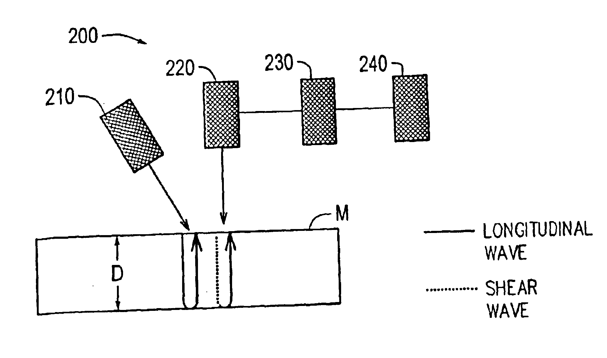
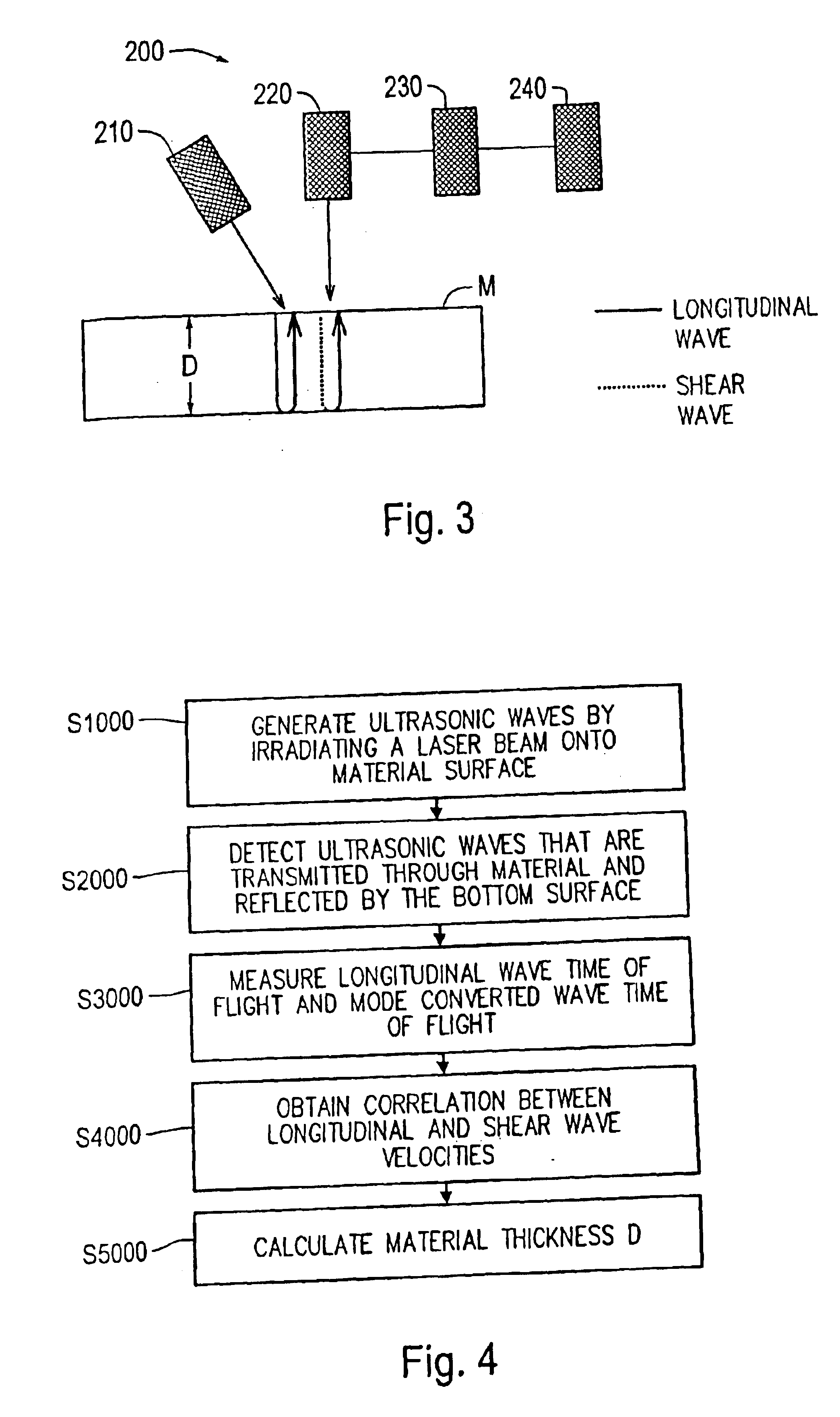
FIG. 3 shows an exemplary embodiment of a material thickness measuring device 200 according to this invention. Furthermore, FIG. 4 shows a flowchart of a material thickness measurement method according to this invention. Hereafter, embodiments of this invention are described in detail based on FIGS. 3 and 4.

In FIG. 3, the material thickness measuring device 200 includes a laser irradiating device 210, an ultrasonic wave detector 220, a time of flight measuring device 230 and a calculator 240.

The laser irradiating device 210 irradiates a laser beam onto a surface of a material M to be measured. An ultrasonic wave is generated inside the material M by a reaction force of ablation of the material surface, or by a thermo-elastic effect of the material surface (step S1000 of FIG. 4). At this time, ultrasonic longitudinal and shear waves are simultaneously generated inside the material M. After the ultrasonic longitudinal waves which are thus generated are transmitted inside the material ...


PUM

PropertyMeasurementUnit
thicknessaaaaaaaaaa
thicknessaaaaaaaaaa
thicknessaaaaaaaaaa

Abstract

Longitudinal and shear ultrasonic waves are generated inside a material by irradiating a laser beam onto a first surface, e.g., incident surface, of the material. An ultrasonic longitudinal wave and a mode converted wave reflected by a second surface, e.g., a bottom surface, of the material are detected, and times of flight of the ultrasonic longitudinal wave and the mode converted wave are measured. A thickness of the material is measured based on the times of flight and a correlation, obtained in advance, between longitudinal and shear wave velocities of the material and temperature of the material.

Description

BACKGROUND OF THE INVENTION1. Field of InventionThis invention relates to a method and apparatus that measure material thickness using an ultrasonic wave, and particularly to a method and apparatus that are suitable for measuring material thickness in an environment in which temperature of the material significantly changes.2. Description of Related ArtAs a material thickness measurement method, a method is well known in which an ultrasonic wave is transmitted in a material thickness direction and the material thickness is measured from the product of the time of flight and the ultrasonic wave velocity of the material. Many thickness measuring devices using this method are sold in the market. FIG. 1 schematically shows a material thickness measurement principle according to this method. Hereafter, a material thickness measurement method using an ultrasonic wave is explained based on FIG. 1.FIG. 1 shows a conventional thickness measuring device 100. An ultrasonic wave probe 110 const...

Claims


Application Information

Patent Timeline
Patent Type & Authority Patents(United States)
IPC IPC(8): G01B17/02G01N29/00
CPCG01B17/02
Inventor OKUNO, MAKOTOSATO, HIDEOKLEIN, MARVIN B.POUET, BRUNO F.
Owner OPTECH VENTURES
Why Eureka
Try Eureka