Heated nozzle assembly

a technology of nozzle assembly and heat dissipation nozzle, which is applied in the direction of paper hanging, manufacturing tools, transportation and packaging, etc., can solve the problems of solder paste on printed circuit boards that has not been proven to be effective for mass production, and the solder paste on printed circuit boards to dry ou

Inactive Publication Date: 2005-01-04
FREESCALE SEMICON INC
View PDF9 Cites 3 Cited by
  • Summary
  • Abstract
  • Description
  • Claims
  • Application Information

AI Technical Summary

Problems solved by technology

However, these techniques have not been proven to be effective for mass production.
While this technique can easily be

Method used


Image

  • Heated nozzle assembly
  • Heated nozzle assembly
  • Heated nozzle assembly

Examples


Embodiment Construction

As required, detailed embodiments of the present invention are disclosed herein; however, it is to be understood that the disclosed embodiments are merely exemplary of the invention, which can be embodied in various forms. Therefore, specific structural and functional details disclosed herein are not to be interpreted as limiting, but merely as a basis for the claims and as a representative basis for teaching one skilled in the art to variously employ the present invention in virtually any appropriately detailed structure. Further, the terms and phrases used herein are not intended to be limiting; but rather, to provide an understandable description of the invention. The terms a or an, as used herein, are defined as one or more than one. The term plurality, as used herein, is defined as two or more than two. The term another, as used herein, is defined as at least a second or more. The terms including, and / or having, as used herein, are defined as comprising (i.e., open language).

A ...


PUM

PropertyMeasurementUnit
Temperatureaaaaaaaaaa
Forceaaaaaaaaaa
Speedaaaaaaaaaa

Abstract

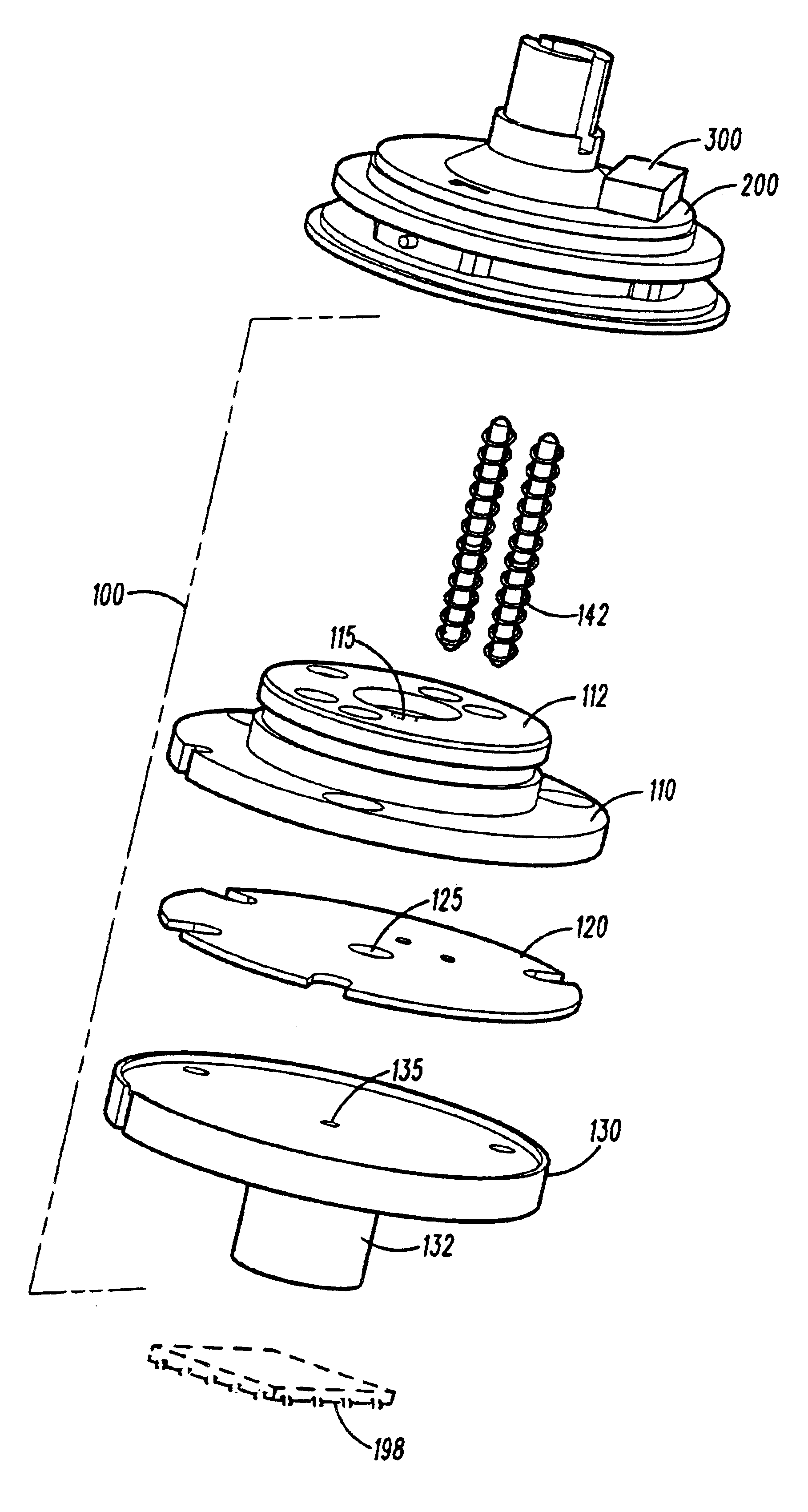
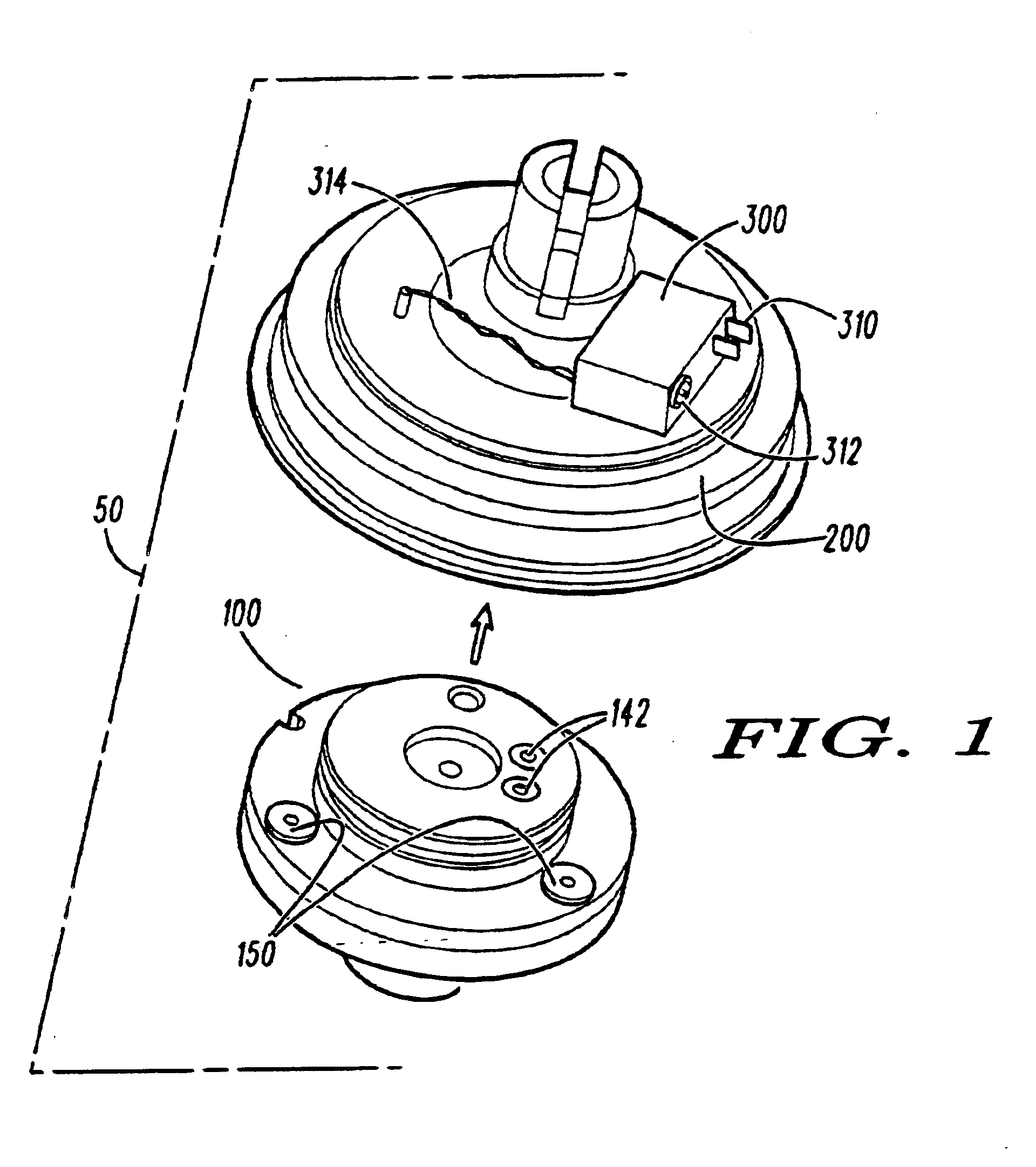
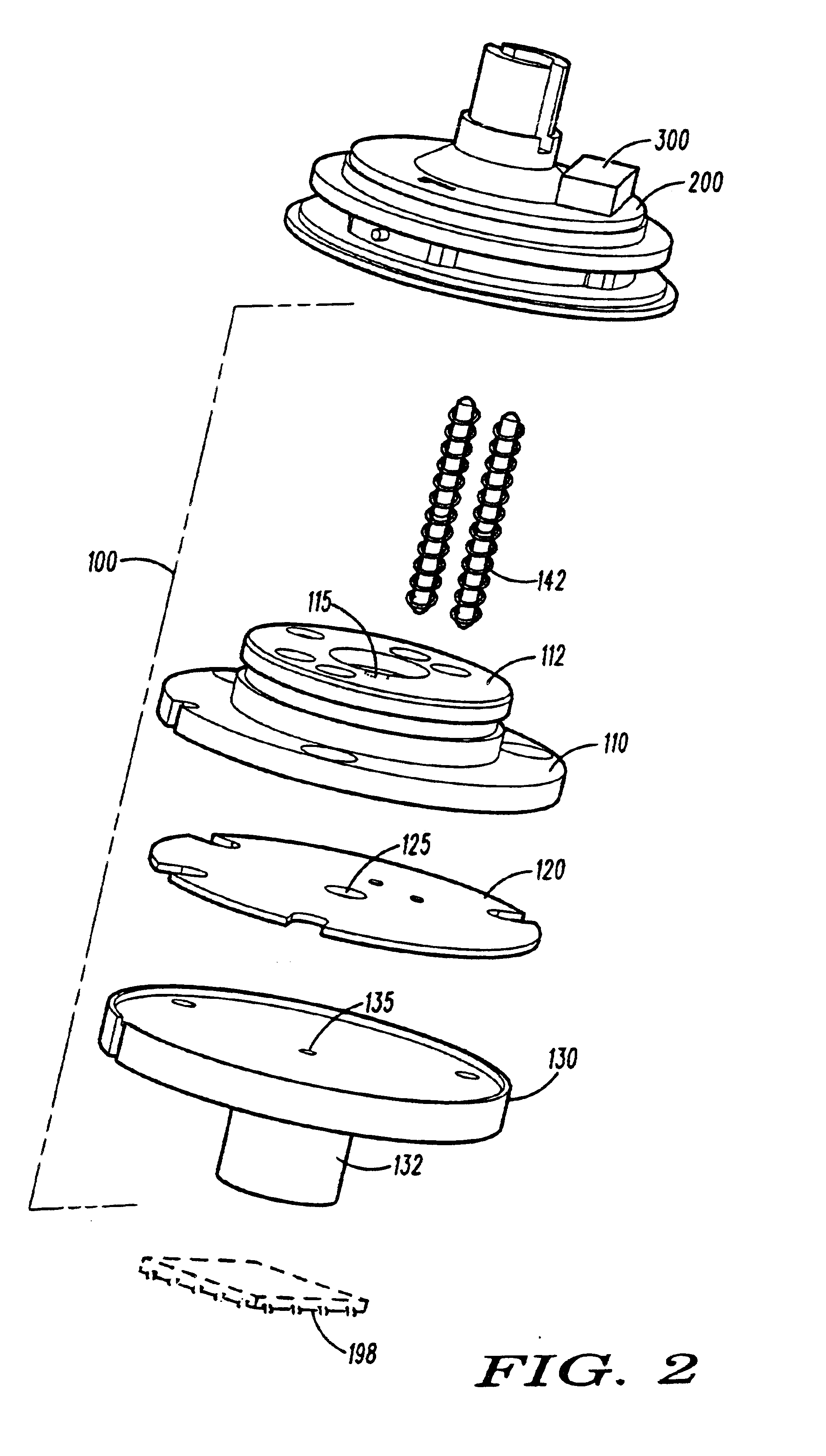
An interface block (300) carries a removable electrical connection (310, 312) that can be quickly connected and removed from a high speed machine for picking and placing electronic components. The interface block is attached to a vacuum ported tool changer (200) which further couples to a heated end effector (100) to create a removable heated nozzle assembly (50). The entire assembly can be easily plugged into and removed from a high speed placement machine.

Description

FIELD OF THE INVENTIONThis invention relates generally to automated placement of small electronic components. More particularly, this invention relates to the use of a easily removable heated end effector on placement systems to preheat an adhesive on electronic components.BACKGROUND OF THE INVENTION“Chip shooters” or “Pick-and-Place” machines rapidly place small electronic components such as resistors, capacitors and integrated circuit packages on a printed circuit board. The placement of components on the board can reach rates of more than 40,000 chips per hour. These machines pick up and accurately locate the component on the end of a vacuum nozzle. Chip shooters use one of two basic designs to place components. The most common is a turret drive with multiple heads around the outside of the turret. A feeder carriage is placed in the back of the machine that moves back and forth to put the correct component under the turret. As the turret spins, the component is picked up from the...

Claims


Application Information

Patent Timeline
IPC IPC(8): H05K13/04
CPCH05K13/0408H05K13/0465Y10S156/941Y10T29/53191Y10T156/1744Y10T156/19Y10T156/1783Y10T156/178Y10T156/1788H05K13/0409
Inventor MOK, SWEE M.DANVIR, JANICE M.WU, CHI-HAUR
Owner FREESCALE SEMICON INC
Why Eureka
Try Eureka