
Single piece pod shield for vertical plenum wafer processing machine

a vertical plenum wafer processing machine and single-piece technology, applied in vacuum evaporation coatings, electrolysis components, coatings, etc., can solve the problems of affecting the operation of equipment, affecting the processing of substrates in the chamber, and requiring equipment to be shut down, so as to facilitate optimal processing and reduce the overall cost of machine operation.

Inactive Publication Date: 2005-01-04
TOKYO ELECTRON LTD
View PDF8 Cites 20 Cited by
  • Summary
  • Abstract
  • Description
  • Claims
  • Application Information

AI Technical Summary

Benefits of technology

A particular objective of the invention is to provide chamber shields for a sputtering apparatus that will reduce the overall cost of operation of the machine.
Another objective of the invention is to provide a chamber shield for a sputtering apparatus that facilitates optimal performance of the process being performed in the sputtering apparatus.

Problems solved by technology

These coatings must be periodically removed or they will eventually flake off and contaminate substrates being processed in the chamber or interfere with the operation of the equipment.
Cleaning of the fixed components of the processing chamber is time consuming, requiring the equipment to be shut down, and subtracting from the productivity of the equipment.
The complicated structure of processing chambers has resulted in the chamber shields being made in a number of parts.
As a result, the number and shapes of the chamber shields have added to the removal and replacement times for the shields and limited the productivity savings that the shields provide.
In addition to contributing to the down-time of the machine that is needed to change chamber shields, replacements for complex shield systems are expensive and, in addition to the loss of valuable production time, add to the machine's maintenance costs.
High speed processing machines such as those of the vertical, split-plenum type, in which the processing chambers are formed in two halves on opposite sides of a rotating, index-wheel or index-plate, multiple-wafer holder, impose additional difficulties on the designs of chamber shields.

Method used


Image

  • Single piece pod shield for vertical plenum wafer processing machine
  • Single piece pod shield for vertical plenum wafer processing machine
  • Single piece pod shield for vertical plenum wafer processing machine

Examples


Embodiment Construction

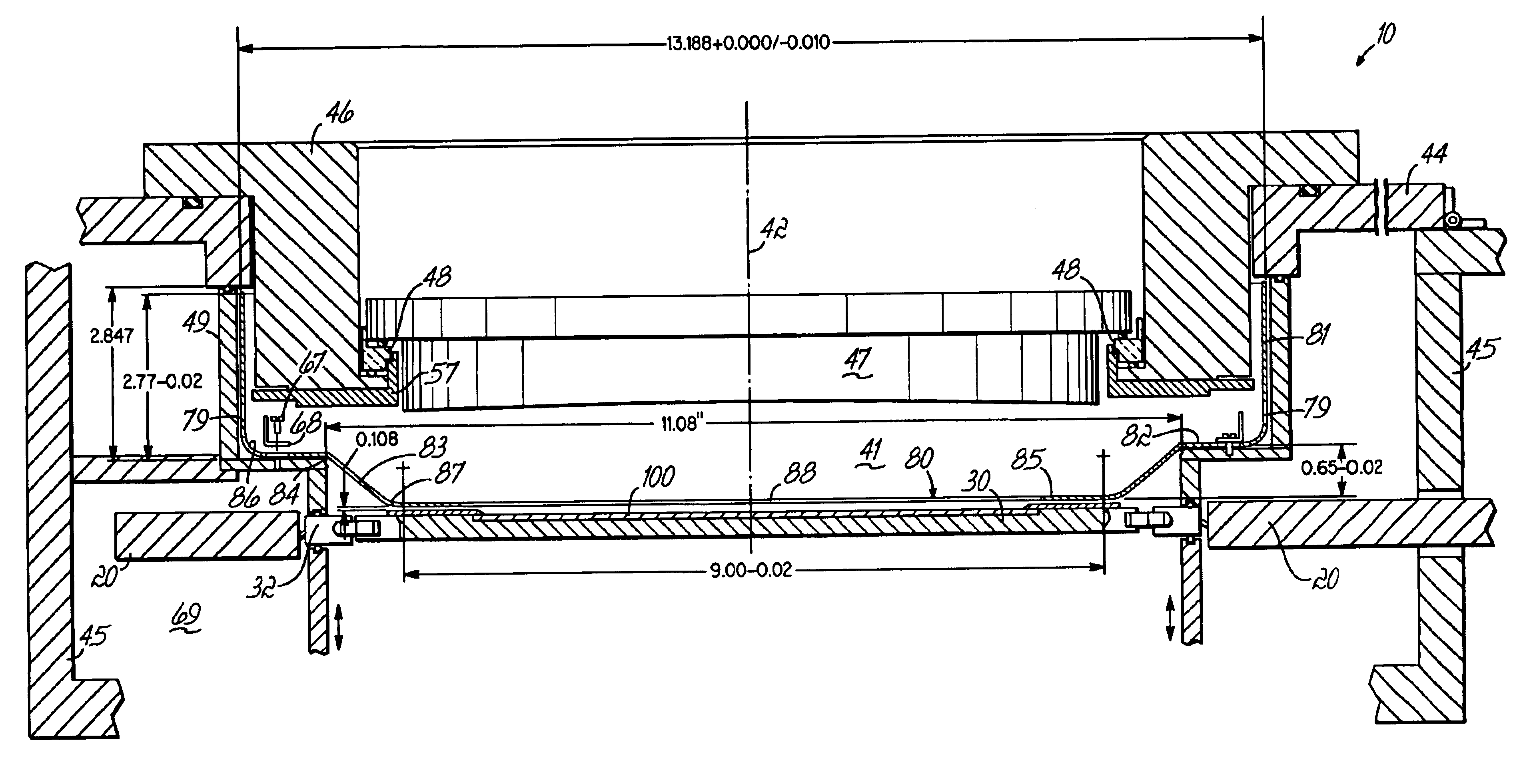
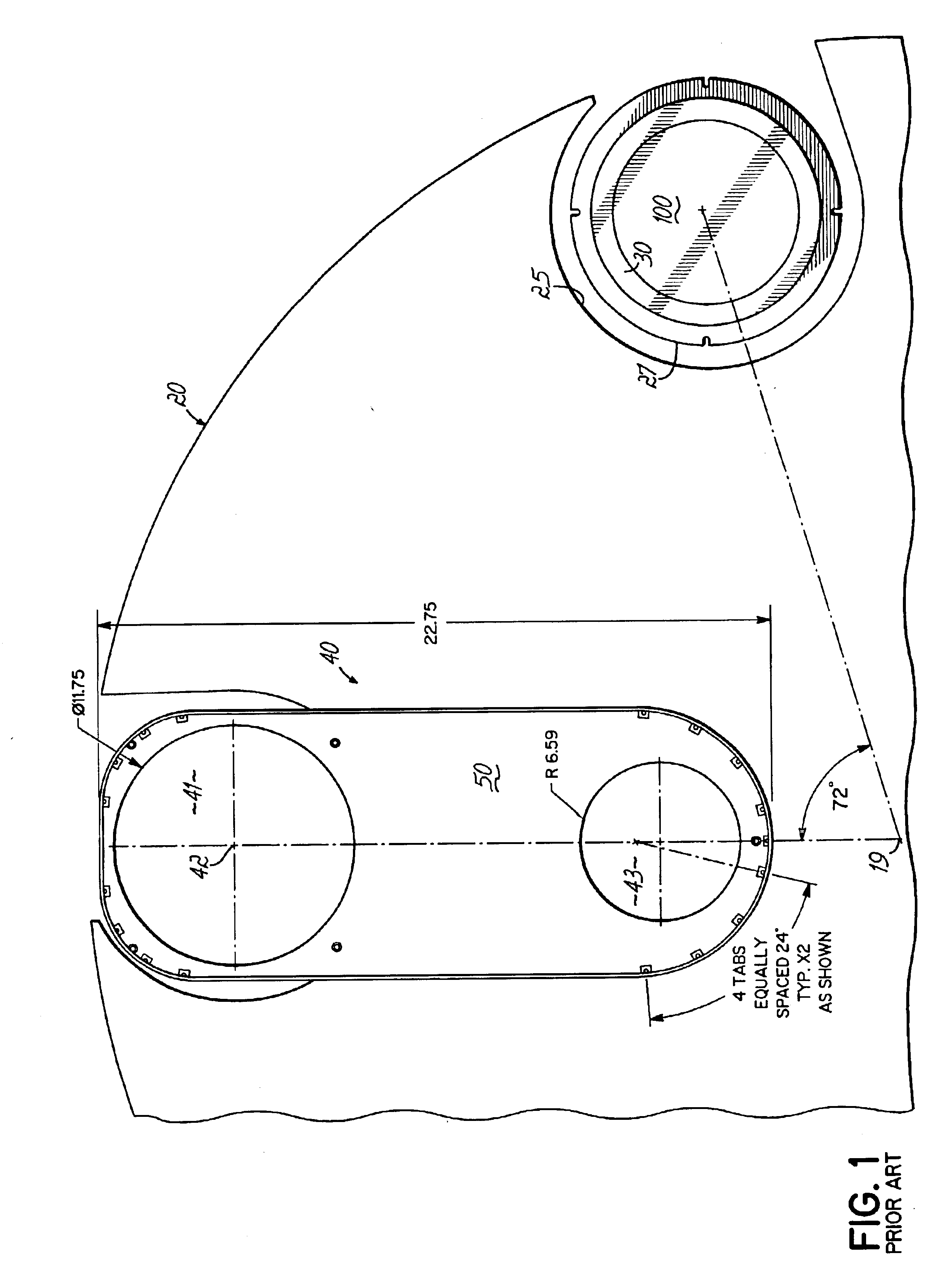
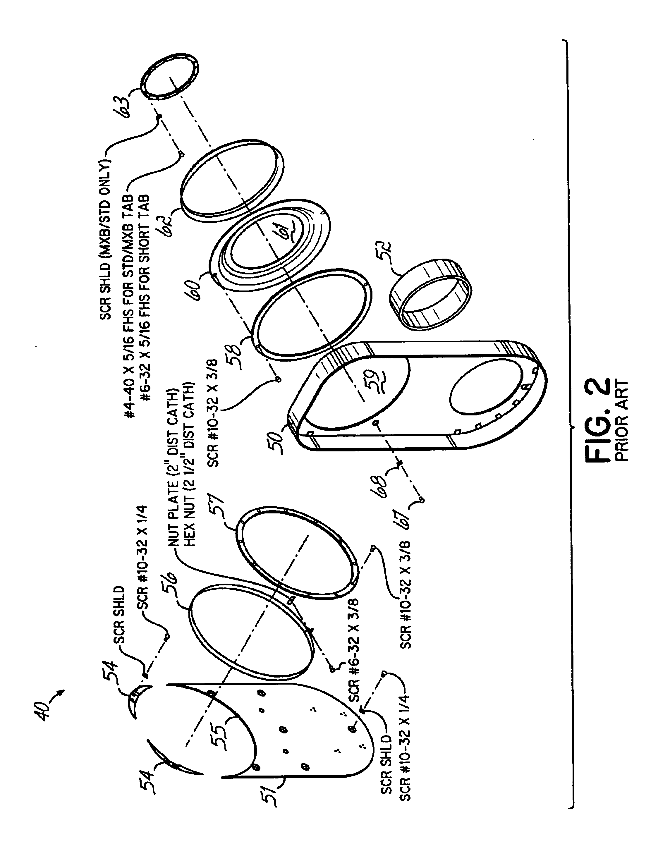
In FIG. 1, a portion of a sputter processing apparatus 10 of the prior art is illustrated, showing an index plate 20, similar to the plate 20 of U.S. Pat. No. 5,820,329, in relation to a chamber-shield system 40. The plate 20 rotates about its axis 19 and has five wafer-holder openings 25 therein equally spaced around the axis 19 and in each of which is resiliently mounted a sealing ring 27 to which is mounted a wafer holder 30 that supports a wafer 100 for processing. The shield system 40 has components centered on the centerline 42 of a processing chamber 41 and components that are extend to and around a gate valve opening 43 to a vacuum pumping system (not shown). One of the five wafer holders 30, which is not shown, is centered on the centerline 42 of the chamber 41. A second one of the five holders 30 is illustrated spaced 72° about the axis 19 from the chamber 41, where it is centered at either another processing station or a load lock station, which is omitted from the illust...


PUM

PropertyMeasurementUnit
Lengthaaaaaaaaaa
Lengthaaaaaaaaaa
Lengthaaaaaaaaaa

Abstract

A replacement chamber shield is provided for a wafer processing machine that replaces many prior art shield components with a single piece shield. The shield is particularly suitable for use in a processing chamber of a vacuum processing machine of a type for processing a wafer in a vertically-oriented split-plenum, such as machines of the type described in U.S. Pat. Nos. 4,909,695 and 4,915,564 and the machine marketed under the trademark ECLIPSE MARK II by Tokyo Electron Limited. The shield is formed of sheet material formed into an axially-extending cylindrical sidewall that turns radially inwardly into an annular shoulder that oppositely turns into an at least partially axially-extending section that further turns oppositely back radially inwardly into an annular disc having a central circular opening that is larger in diameter than the given wafer diameter. Advantageous dimensions and geometric relationships to components of the machine are described and claimed.

Description

FIELD OF THE INVENTIONThis application relates to chamber shields for wafer processing machines of the type described in U.S. Pat. Nos. 4,909,695 and 4,915,564, both hereby expressly i corporated herein by reference, and of the types described in U.S. Pat. No. 5,516,732 and U.S. patent application Ser. No. 09 / 725,823, both also hereby expressly incorporated herein by reference. Details of structure within chambers of such machines are also described in U.S. Pat. Nos. 5,820,329, 6,143,147 and 6,258,228, each also hereby expressly incorporated herein by reference. A machine of this type has been marketed under the trademark ECLIPSE MARK II by Applicant's assignee, Tokyo Electron Limited. This application particularly relates to shield used in sputtering chambers of such machines, particularly in sputter deposition chambers, to shield chamber walls and other structures around the perimeters of wafers being processed in such chambers.BACKGROUND OF THE INVENTIONSputtering equipment that ...

Claims


Application Information

Patent Timeline
IPC IPC(8): C23C14/56C23C14/34H01J37/32H01J37/34
CPCC23C14/34H01J37/3441H01J37/34C23C14/564
Inventor LAWSON, JOHNIRWIN, DALECHERVENAK, STEVE
Owner TOKYO ELECTRON LTD
Learn More