Oil field separation facility control system utilizing total organic carbon analyzer

a technology of total organic carbon and control system, which is applied in the direction of separation process, ion exchanger, borehole/well accessories, etc., can solve the problems of oil stream being rejected by the operator of the pipeline and/or the refinery, loss of oil present in the water stream, and inconvenient sampling of the separated water stream. , to achieve the effect of accurate sampling

Inactive Publication Date: 2005-01-04
CONOCOPHILLIPS CO
View PDF13 Cites 15 Cited by
  • Summary
  • Abstract
  • Description
  • Claims
  • Application Information

AI Technical Summary

Benefits of technology

Another object of the present invention is to provide a system for more accurately sampling the separated water stream produced from an oil field separation facility.
Still another object of the present invention is to provide a system for analyzing the amount of oil in a water stream that does not require high rates of dilution of the separated water sample.
Yet another ob

Problems solved by technology

If the separation facility does not properly separate the oil and water, either the oil stream exiting the facility will contain too much water or the water stream exiting the facility will contain too much oil.
If too much water is contained in the separated oil stream exiting the facility, the oil stream may be rejected by the operator of the pipeline and/or the refinery.
If too much oil is contained in the separated water stream exiting the facility, the value of the oil present in the water stream is lost because typically the separated water stream is simply discharged or reinjected into the subterranean formation for water flooding.
For large separation facilities, an oil content of just 5,000 ppmw in the separated water stream can result in a yearly oil loss valued at several million dollars.
Thus, measuring the oil content of the separated water stream on an infrequent basis may not provide a reliable indication of oil content because limited duration spikes in the oil content may not be accounted for.
Also, infrequent measurement of the oil content does not allow the separation facility to be controlled in a dynamic manner which can reduce or eliminate spikes in the oil concentration.
An additional drawback of many conventional methods for measuring the oil content of a separate water stream is that past methods of sampling the separ

Method used


Image

  • Oil field separation facility control system utilizing total organic carbon analyzer
  • Oil field separation facility control system utilizing total organic carbon analyzer
  • Oil field separation facility control system utilizing total organic carbon analyzer

Examples


Embodiment Construction

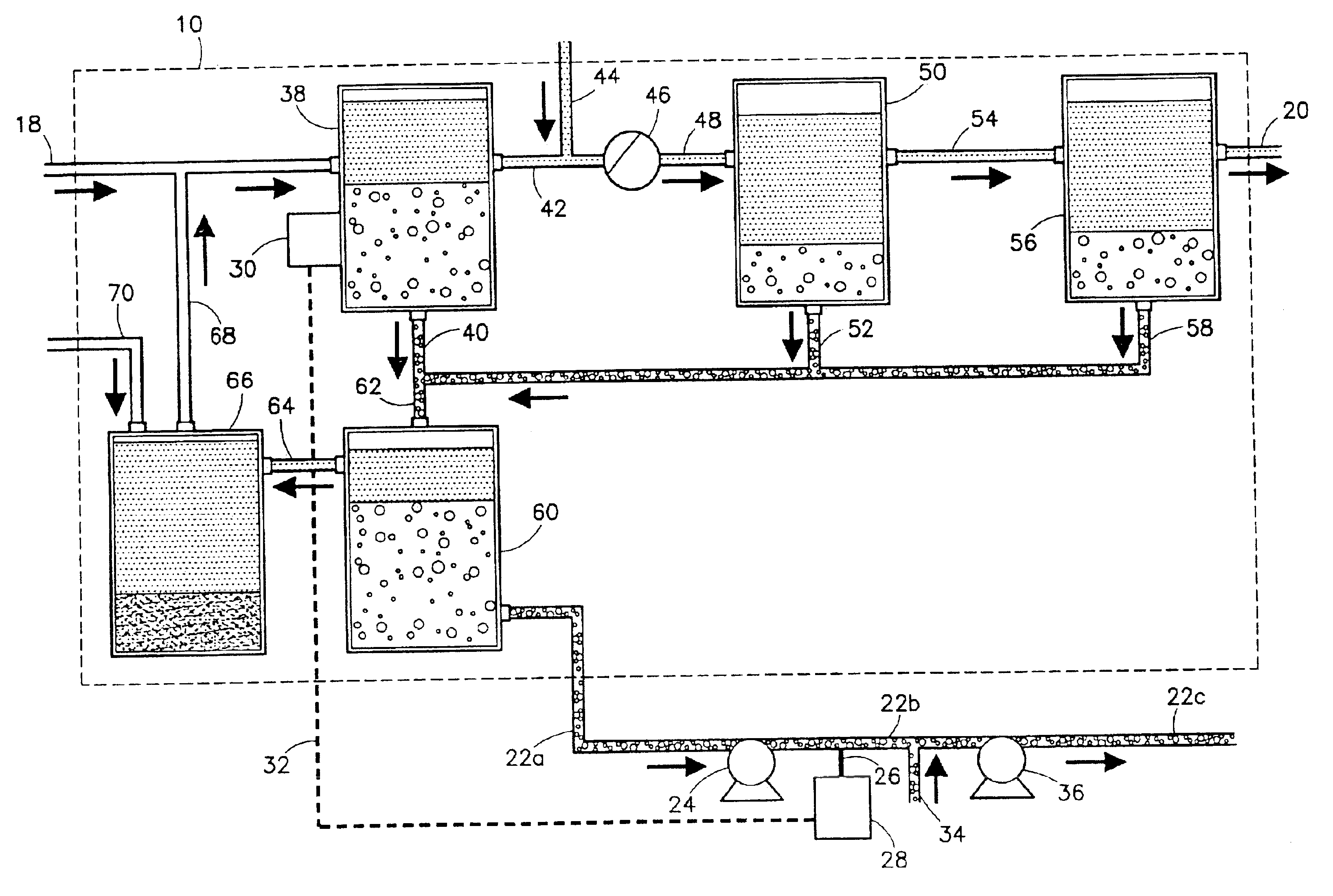
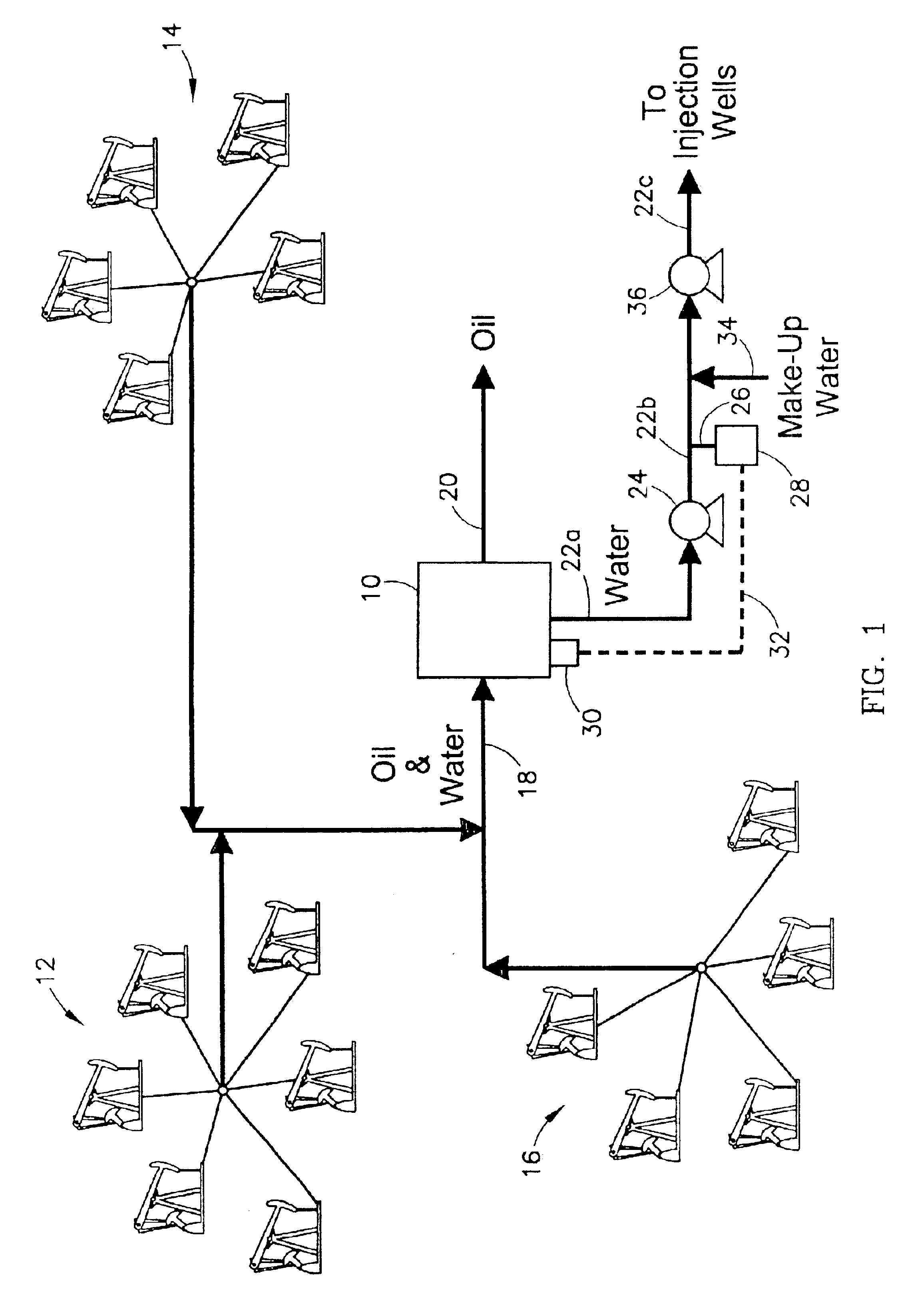
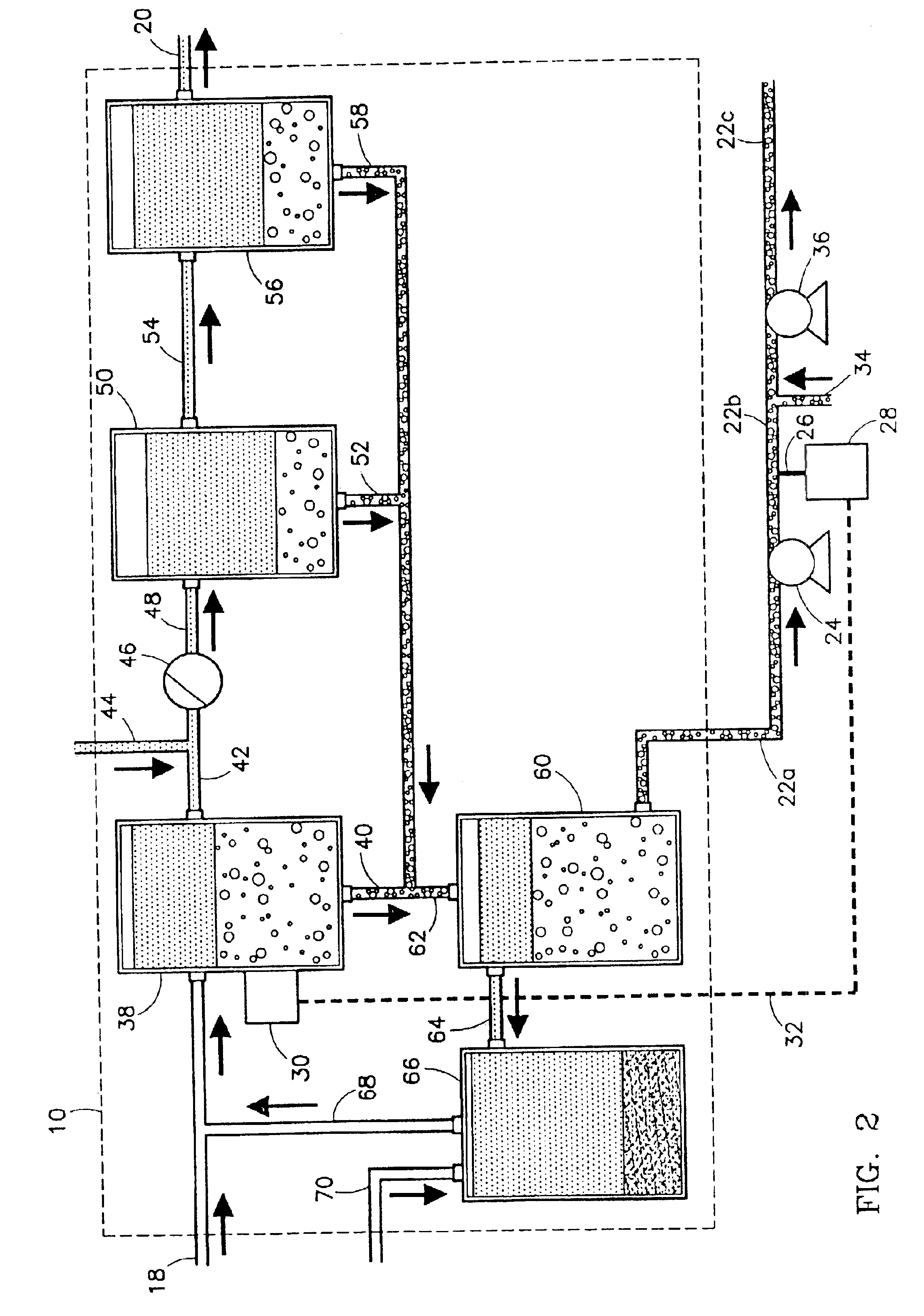
Referring initially to FIG. 1, an oil field separation facility 10 is illustrated as servicing several different oil fields, each including a number of individual wells. Produced oil and water from a first oil field 12, a second oil field 14, and a third oil field 16 are combined in a main conduit 18 and carried to separation facility 10. Although FIG. 1 shows separation facility 10 servicing only 16 individual wells, it is more typical for oil field separation facility 10 to service a greater number of individual wells (e.g., 50-500 wells). In separation facility 10, the produced oil and water mixture is separated into an oil-rich stream exiting separation facility 10 via an oil conduit 20 and a water-rich stream exiting separation facility 10 via a water conduit 22a.

Water conduit 22a carries the water-rich stream to an agitating means 24 which is operable to increase the turbulence of the water-rich stream. Agitating means 24 can be any apparatus for enhancing the physical mixing...


PUM

PropertyMeasurementUnit
Timeaaaaaaaaaa
Timeaaaaaaaaaa
Volumeaaaaaaaaaa

Abstract

An oil field separation facility utilizing a total organic carbon analyzer to help maintain consistently acceptable levels of oil and water separation. The facility separates a produced oil and water mixture into an oil-rich stream and a water-rich stream. The total organic carbon analyzer measures the total organic carbon content of the water-rich stream. The measured total organic carbon content of the water-rich stream can then be used to adjust an operating parameter of the separation facility.

Description

BACKGROUND OF THE INVENTION1. Field of the InventionThe present invention relates generally to facilities for separating oil and water present in a fluid mixture produced from a subterranean well. In another aspect, the invention concerns a system for controlling an oil field separation facility by measuring the amount of oil present in the separated water stream.2. Description of the Prior ArtOil wells frequently produce water along with oil. In many instances the commonly produced oil and water phases are separated in the field prior to transporting the oil to a major pipeline or refinery facility. Each in-the-field oil separation facility may service a number of individual wells. Thus, large volumes of oil and water may be passed through the separation facility every day. If the separation facility does not properly separate the oil and water, either the oil stream exiting the facility will contain too much water or the water stream exiting the facility will contain too much oil....

Claims


Application Information

Patent Timeline
IPC IPC(8): B01D17/02C02F1/40B01D17/00E21B43/34G01N33/18
CPCB01D17/005E21B43/34G01N33/1846B01D17/0208B01D17/0214B01D17/045B01D17/06
Inventor FEIERABEND, JERRY GLYNNBLUMER, DAVID J.AUSTIN, THOMASJOHNSON, SUNG-ISLOAN, RICHARD D.NEUGEBAUER, BRADLEY A.HEALD, RANDALL LEEJERLING, MARK F.BRADSHAW, PETER M.
Owner CONOCOPHILLIPS CO
Why Eureka
Try Eureka