
Continuous formation of center filled gum

Inactive Publication Date: 2005-01-04
INTERCONTINENTAL GREAT BRANDS
View PDF7 Cites 72 Cited by
  • Summary
  • Abstract
  • Description
  • Claims
  • Application Information

AI Technical Summary

Benefits of technology

It is an object of the present invention to provide improved mechanisms and systems for producing center-filled gum products. It is also an object of the present invention to provide improved systems for continuously producing pieces of center-filled gum from continuous ropes or strands of gum material.
With the present invention, liquid-filled pieces of gum are formed in a faster and more efficient manner than with known processes and systems.

Problems solved by technology

Although many of these known mechanisms and processes operate satisfactorily and produce acceptable results, there are a number of mechanical and processing concerns which need improvement.
One of the difficulties in the art of gum manufacturing is the fact that the gum products are tacky and have a tendency to stick or adhere to molds and operating machinery.
At these low temperatures, however, the costs of operation increase and the operation of machinery become more difficult.
For example, oils and greases can congeal into non-fluid masses, thereby reducing the lubricating ability of the materials and causing increased friction of moving parts.
This also causes additional heat load on the moving parts resulting in less efficient high-speed operation.
Cooling all parts of the apparatus, however, creates significant additional expense, as well as further mechanical and friction difficulties in the operation of the machinery.
It has also been known to be problems with rotating gum forming equipment to effectively feed a rope or strand of gum material into the rotating machinery and to insure that all of the formed pieces of gum material are removed or stripped from the rotating machinery.
This creates unnecessary waste of material and, if the material has a liquid portion, can result in “leakers” which can cause stoppage and / or breakdowns of the machinery, as well as undesirable final products.

Method used


Image

  • Continuous formation of center filled gum
  • Continuous formation of center filled gum
  • Continuous formation of center filled gum

Examples


embodiment 160 ′

An alternate embodiment 160′ of the stripper member is shown in FIG. 12. In this embodiment, the stripper member includes a stripper finger 162 and a tubular member 172 which has a plurality of openings 174 therein for ejection of cooled air. The stripper member of 160′ can be attached to the die forming mechanism 22 in any conventional manner.

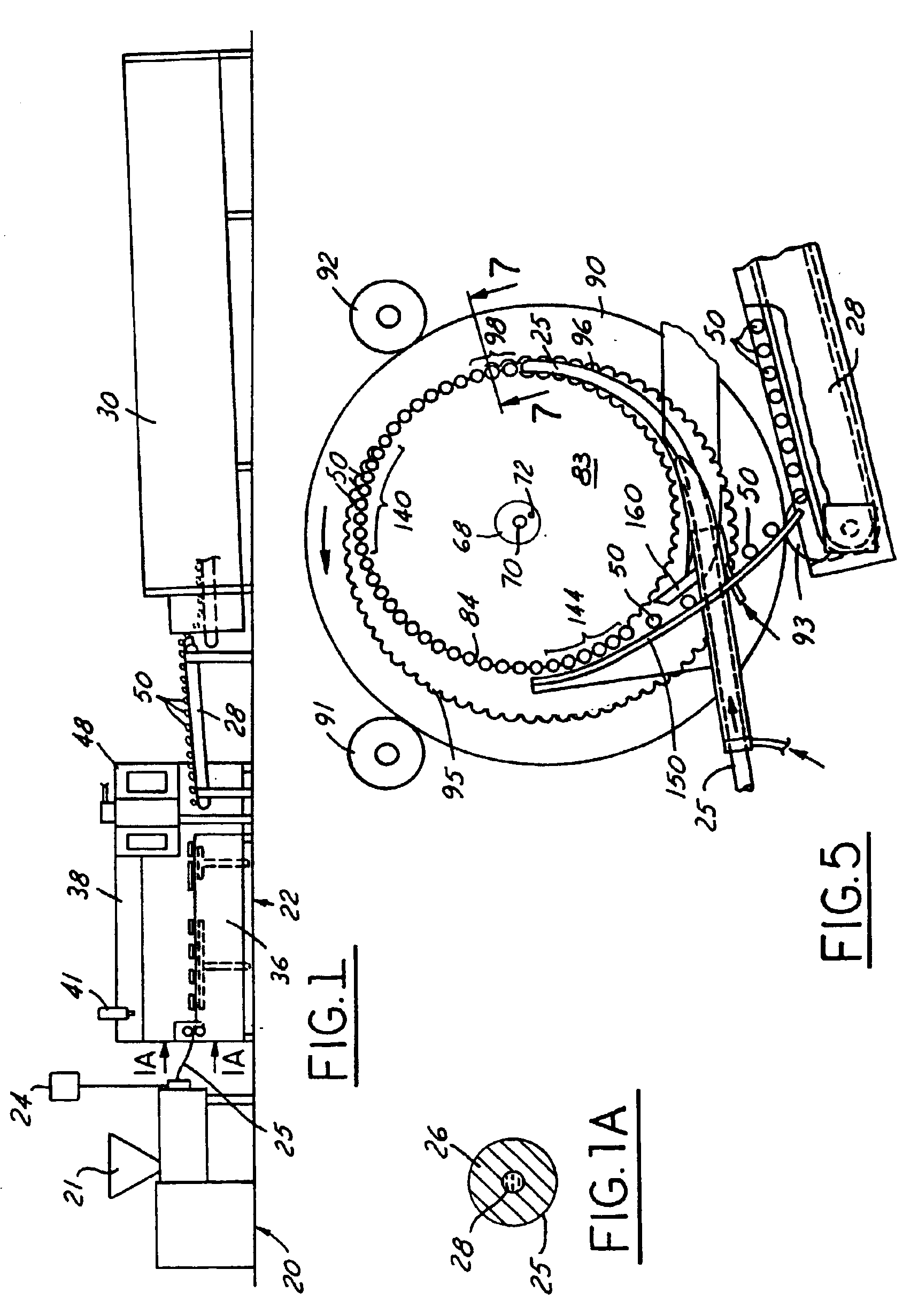
The feed chute member 60 is particularly shown in FIGS. 13-16. FIG. 13 shows the location of installation of the feed chute member relative to the rotating die ring and cutter ring members, while FIGS. 14, 15 and 16 are side, top and bottom views, respectively, of the preferred feed chute member.

The feed chute member 60 provides conveyance of the rope of gum material 25 from the forming and sizing table section 36 to the individual piece forming section on the drum member 60 in the system. Without the feed chute member 60, conveying the end of the extruded rope member 25 and inserting it into position between the diverging die half members on ...


PUM

PropertyMeasurementUnit
Angleaaaaaaaaaa
Areaaaaaaaaaaa

Abstract

Method and system for continuously producing pieces of liquid-filled gum material. An extruded rope of liquid-filed gum is sized and separated into individual pieces of gum. A rotating drum mechanism having a die ring and cutter ring with mating die members separate the rope of gum material into individual pieces. Pairs of cam-operated plunger members compress and form the pieces of gum material in the die cavities. Angled grooves in the die members prevent portions of the gum pieces from being chipped-off during formation. Guide pin members are positioned between rider members on the plunger members. A feed chute with air assist transfers the gum rope from a sizing table to the rotating drum mechanism. A stripper member insures that the formed pieces of gum material are removed from the drum mechanism. Portions of the drum mechanism can be selective heated and cooled, or not cooled at all. The invention provides a more efficient system for continuous, high production operation.

Description

TECHNICAL FIELDMethod, system, and apparatus for continuously forming center-filled gum, particularly for continuously forming individual sealed pieces of liquid-filled gum from a continuous rope or strand.BACKGROUND OF THE INVENTIONLiquid or center filled gum and other confectionery products are in popular demand today. These products have a hard or solid exterior portion or shell and a soft or liquid center. The outer portion can be chewing gum or bubble gum of some type, while the liquid center portion can be a flavored material typically having a syrup-like consistency.There are numerous mechanisms and systems known today for forming liquid-filled gum and other confectionery products. One of these systems is shown, for example, in U.S. Pat. No. 3,857,963 to Graff et al. Although many of these known mechanisms and processes operate satisfactorily and produce acceptable results, there are a number of mechanical and processing concerns which need improvement. In particular, there i...

Claims


Application Information

Patent Timeline
IPC IPC(8): A23G3/02A23G4/04A23G4/02A23G3/20A23G4/00A23G3/06A23G3/12A23G7/02B30B11/08B30B11/20B30B15/34
CPCA23G3/0247A23G3/0289A23G3/06A23G3/12A23G3/2015A23G3/2061B30B15/34A23G4/043A23G4/205A23G7/02B30B11/08B30B11/20A23G4/025
Inventor BUNKERS, JOSEPH M.DUGGAN, JAMES
Owner INTERCONTINENTAL GREAT BRANDS
Features
  • Generate Ideas
  • Intellectual Property
  • Life Sciences
  • Materials
  • Tech Scout
  • Unparalleled Data Quality
  • Higher Quality Content
  • 60% Fewer Hallucinations
Learn More