Digital signal to pulse converter and method of digital signal to pulse conversion

Inactive Publication Date: 2005-01-04
AISIN SEIKI KK
View PDF9 Cites 16 Cited by
  • Summary
  • Abstract
  • Description
  • Claims
  • Application Information

AI Technical Summary

Benefits of technology

In view of the foregoing, it is an object of the present invention to provide a vibration reducti

Problems solved by technology

However, if a control apparatus of the SR motor is an open loop, a torque fluctuation of the electric motor causes a resonance vibration for the SR motor or the vehicle body when a vehicle mounting on the SR motor has a resonance characteristic by an effect of a shaft, a twist of a tire, and a spring of a suspension, e.t.c.
As the rotational unevenness gives little by little a

Method used


Image

  • Digital signal to pulse converter and method of digital signal to pulse conversion
  • Digital signal to pulse converter and method of digital signal to pulse conversion
  • Digital signal to pulse converter and method of digital signal to pulse conversion

Examples


Example

(First Embodiment)

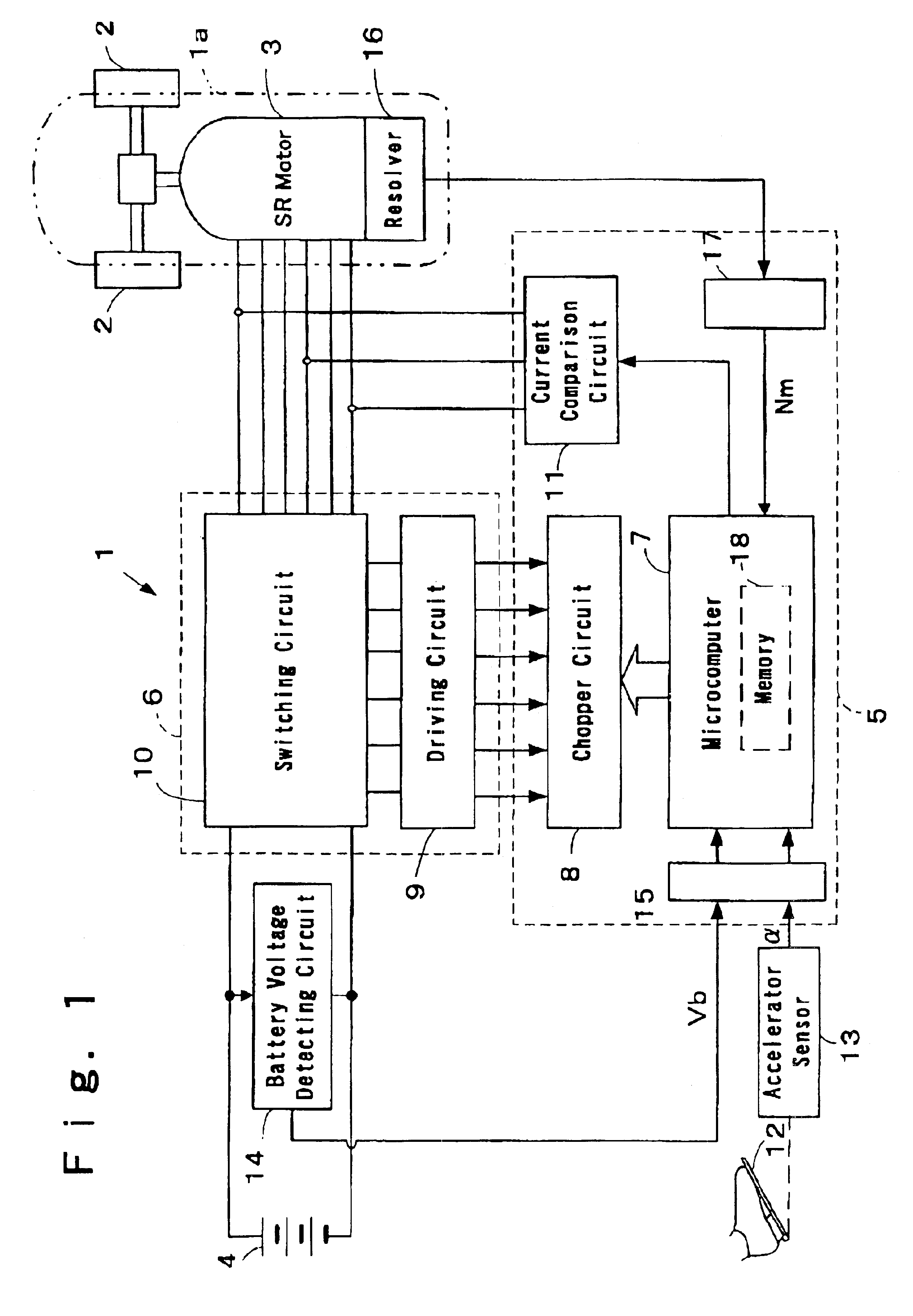
The electric vehicle 1 includes an SR (Switched Reluctance) motor 3 such as an electric motor of the power train source outputting a driving torque at a driving wheel 2. The SR motor 3 is mounted on a predetermined location of a part room of a vehicle body 1a in the electric vehicle 1. However, FIG. 1 only shows the location of the SR motor in the vehicle body 1a, a size of the SR motor shown in FIG. 1 is not to scale. A battery 4 is used e.g. a fuel electric battery or rechargeable battery, etc. The SR motor 3 is controlled by an ECU (Electronic Control Unit) 5 via an inverter 6. The ECU 5 comprises a microcomputer 7 and a chopper circuit 8. Further, the microcomputer 7 includes a filter means, a correcting means, and a control means.

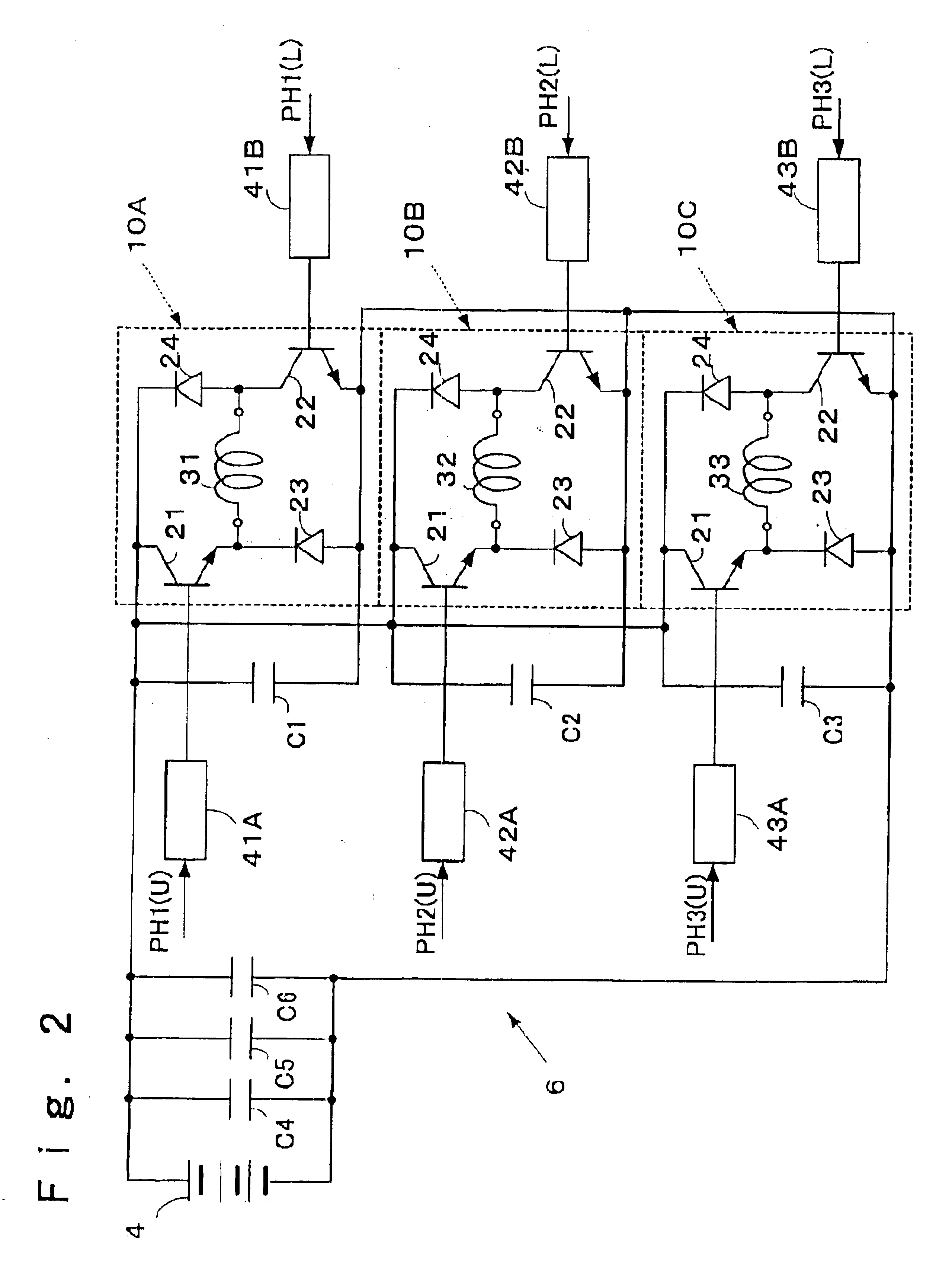
The inverter 6 connects to the battery 4 supplying a battery voltage, an output side of the inverter 6 electrically connects to the SR motor 3. The inverter 6 comprises a driving circuit 9 and a switching circuit 10. The SR motor 3 is...

Example

(Second Embodiment)

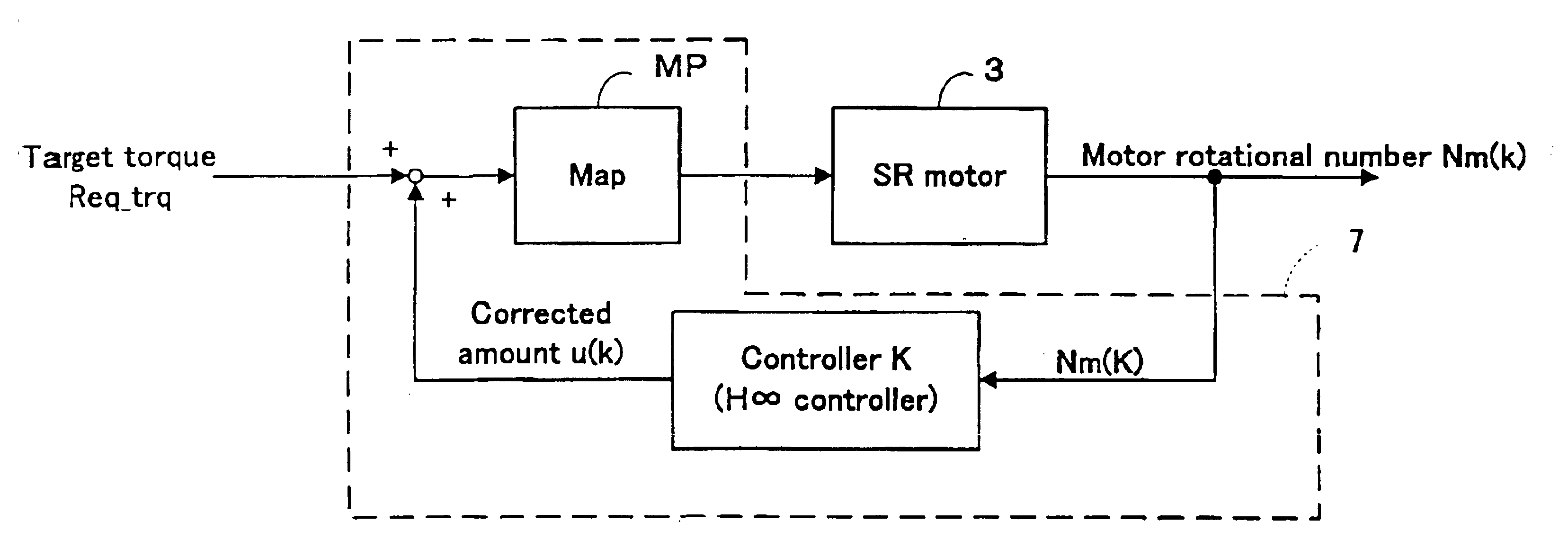
A second embodiment will be explained hereinafter referring to FIGS. 8-15. The second embodiment differs from the first embodiment in that it adopts an H∞ (H infinity) control such as the vibration reduction control in the feed back control. Portions of the explanation which are the same as the first embodiment are omitted in the explanation of the second embodiment.

Generally, a controller for reducing effect for a characteristic fluctuation of a control system by an H∞ control theory is designed, i.e. the controller can be secured, with a robust stability. In a standard H∞ control problem which addresses a robust stability problem (securement of the robust stability), a sensibility characteristic of the control system (a vibration reduction and a torque tracking performance) is assured for a nominal plant. On the other hand, the sensibility characteristic is conservative, it often causes a large languish when a characteristic of the plant (control system) fluctua...


PUM


Abstract

An electric motor such as a driving source of an electric vehicle is controlled by the microcomputer 7. The microcomputer 7 calculates a target torque Req_trq according to a throttle opening degree α, and outputting induction values (a current instruction value I and a angle instruction value θ) obtained referring to a map MP based on the target torque Req_trq (a motor rotational number Nm and a battery voltage Vb), the microcomputer 7 performs a torque control of an SR motor 3. The motor rotational number Nm detected from the SR motor 3 is passed through a band pass filter 51. Passing by the band pass filter 51, a signal data of the extracted 0.1-50 Hz is executed a PD calculation process 52, the calculated corrected amount PD_out is subtracted from the target torque Req_trq.

Description

CROSS REFERENCE TO RELATED APPLICATIONSThis application is based on and claims priority under 35 U.S.C. §119 with respect to Japanese Patent Application 2000-290703, filed on Sep. 25, 2000 and Japanese Patent Application 2001-183311, filed on Jun. 18, 2001, the entire contents of which are incorporated herein by reference.FIELD OF THE INVENTIONThis invention relates to a vibration reduction control apparatus for an electric motor and a design method of a vibration reduction control for the electric motor.BACKGROUND OF THE INVENTIONRecently, an SR motor such as a motor for driving of an electric vehicle is known. When the SR motor is controlled, the SR motor is controlled so that a throttle opening degree based on an operating signal of an acceleration pedal is larger, and a target torque (an excitation current) is larger.Conventionally, as shown inFIG. 16, the target torque is changed to a current instruction value I and an angle instruction value θ referring to a predetermined map ...

Claims


Application Information

Patent Timeline
IPC IPC(8): B60L11/18F16F15/18F16F15/10G05B11/42G05B5/00G05B5/01G05B23/02B60K1/00B60L15/00G05B11/32G05B13/02G05B13/04H02P29/00
CPCB60L11/1807G05B5/01G05B11/42F16F15/18B60L2220/18Y02T10/7005B60L3/0061B60L7/14B60L15/007B60L15/02B60L15/20B60L2240/14B60L2240/421B60L2240/423B60L2240/547B60L2260/44B60L2270/145H02P25/098H02P29/50Y02T10/72B60L50/51B60L50/60Y02T10/64Y02T10/70
Inventor INAGAKI, HIROYUKIKUZUYA, HIDEKIKATO, HIROAKISEBE, NOBORU
Owner AISIN SEIKI KK
Why Eureka
Try Eureka