Method and apparatus for measuring inductance

a technology of inductance and apparatus, applied in the direction of noise figure or signal-to-noise ratio measurement, instruments, ways, etc., can solve the problem that the skew angle cannot resolve the lane position, and achieve the effect of reducing sensitivity and repeatability of signatures

Inactive Publication Date: 2005-01-04
INDUCTIVE SIGNATURE TECH
View PDF16 Cites 29 Cited by
  • Summary
  • Abstract
  • Description
  • Claims
  • Application Information

AI Technical Summary

Benefits of technology

For multi-lane traffic, a pair of single-turn wire-loops in a complimentary wedge-shaped configuration is ideal for collecting the maximum unambiguos traffic-flow data. This configuration is a hybrid of rectangular wire-loops and blades which gives repeatability of signatures that is characteristic of the blades along with the less-intrusive installation that is characteristic of simple wire-loops. shallow saw-cuts are desirable for a traffic sensor spanning long distances in a pavement surface to prevent the formation of a shear-plane and slot faulting.
A large-aperture wire-loop can detect metallic objects at great distances. The magnetic field generated by a wire-loop is highly directional at...

Problems solved by technology

Similar skew angles are unable to resolve the lane position; however, this is not as important for single traffic lanes as it is for multiple traffic lanes.
Finally, zero skew angles can produce speed and axle-cou...

Method used


Image

  • Method and apparatus for measuring inductance
  • Method and apparatus for measuring inductance
  • Method and apparatus for measuring inductance

Examples


Embodiment Construction

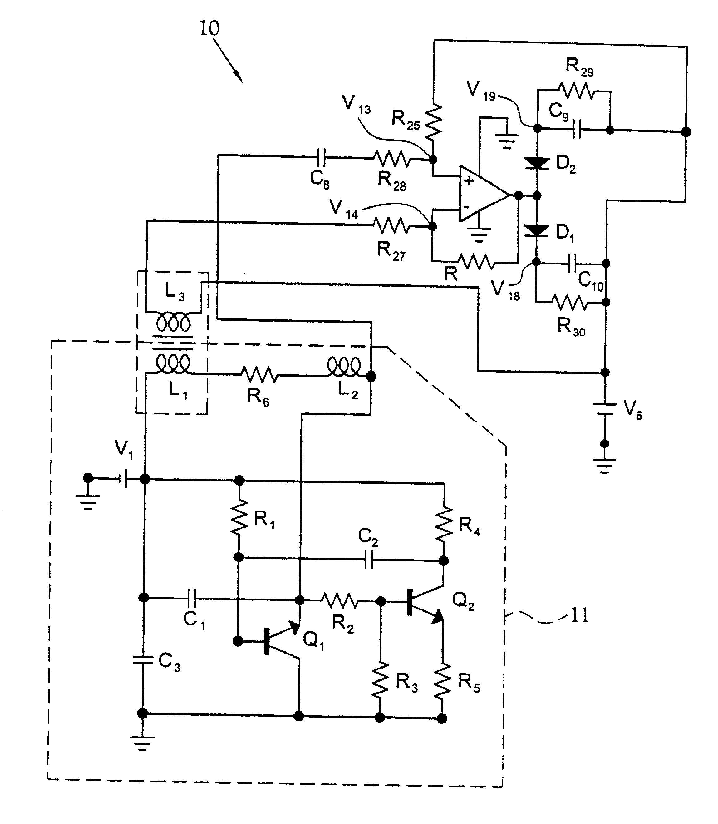
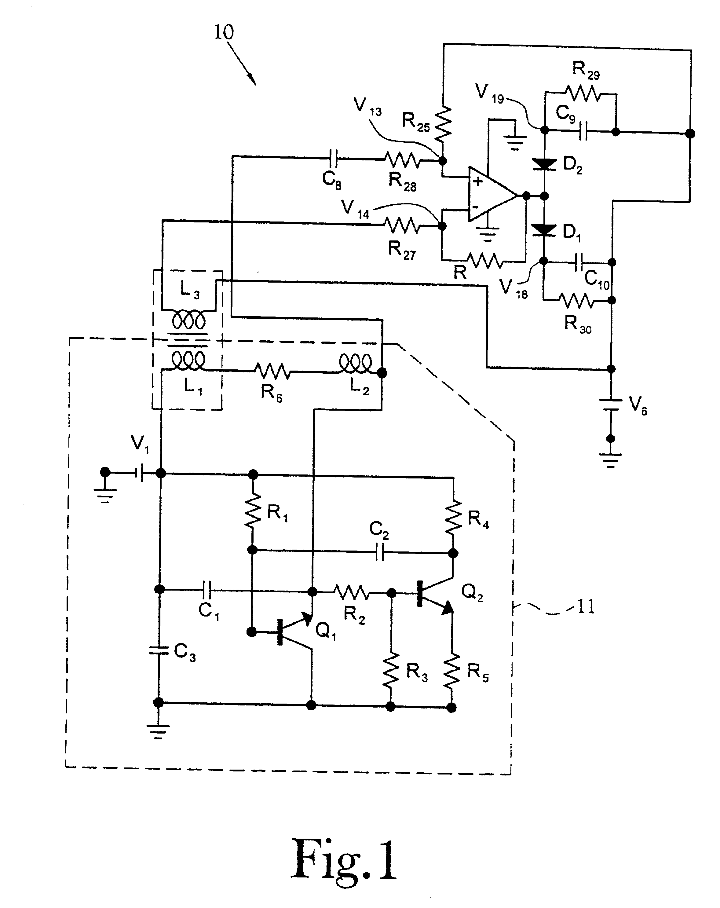
An apparatus and method for measuring the inductance of a wire-loop without direct reference to any particular time-constant or frequency is illustrated generally at 10 in the figures. The apparatus 10 utilizes permeability-modulated carrier referencing to identify the inductive signature of a vehicle passing over a wire-loop.

In a typical LCR circuit, a number of factors are related to the value of the inductance. For example, the frequency is inversely proportional to the square root of the inductance, L. This relationship is a consequence of the direct dependence of the instantaneous rate of change in current flow, δI, upon the value of the inductance as defined in the following equation: δ⁢ ⁢I=VL(1)

Accordingly, frequency is only an indirect indication of this more general relationship because the circuit voltage, V, is in turn a function of current, I, and capacitance, C, as defined in the following equation: δ⁢ ⁢V=IC(1)

A more direct indication of inductance in an LCR oscillator ...


PUM


Abstract

A method and apparatus for measuring changes induced in an inductive field on a wire-loop of an oscillator circuit based upon variations in a current function without the need to measure frequency changes. Induced noise has independent effects upon the current function and voltage function of an inductance measurement circuit. By inductively coupling one input and directly coupling the second input of a comparator circuit to the inductance measurement circuit, the phase of the current function can be adjusted to coincide with the phase of the voltage function. By combining the voltage function with the current function, an output isolating the induced noise from the measured inductance is obtained.

Description

BACKGROUND OF THE INVENTION1. Field of InventionThe present invention relates to an apparatus and method for the measurement of inductance. More precisely the present invention relates to an apparatus and method for the measurement of inductance of vehicles moving in a traffic lane using permeability-modulated carrier referencing.2. Description of the Related ArtIt is well known in the prior art to measure the inductance of a wire-loop, which is part of the frequency determining circuit of an inductance-capacitance-resistance (“LCR”) oscillator, using frequency-counting techniques. Typically, the number of zero-crossings per time increment of the voltage across the terminals of the LCR capacitor is counted. Because the frequency of the LCR oscillator is inversely proportional to the square root of the inductance of the LCR circuit, changes in the inductance of the wire-loop are reflected in changes of the number of zero-crossings counted per time increment.The Class-C wire-loop osci...

Claims


Application Information

Patent Timeline
IPC IPC(8): E01F11/00G01P3/50G01P3/64G01P3/66G01P3/42G01V3/10G08G1/042
CPCE01F11/00G01P3/50G08G1/042G01V3/101G01P3/66
Inventor HILLIARD, STEVEN R.HILLIARD, GEOFFREY W.
Owner INDUCTIVE SIGNATURE TECH
Why Eureka
Try Eureka