Evolute tester for optical surfaces

a tester and optical surface technology, applied in the direction of refractive surface testing, optical elements, instruments, etc., can solve the problems of difficult work, fast” optics are much harder to get right, etc., and achieve the effect of repeatability and high degree of accuracy

Active Publication Date: 2020-09-29
KOKEN TERRELL E
View PDF4 Cites 0 Cited by
  • Summary
  • Abstract
  • Description
  • Claims
  • Application Information

AI Technical Summary

Benefits of technology

[0011]The invention pertains to the testing and characterization of optical or other reflective surfaces. The invention provides a method of testing and characterization which works equally well on concave, flat, convex, and non-conic optical surfaces, and which does not require that a master surface be first produced. The method is automatic and requires little human intervention. It eliminates the need for fallible human judgment of the character and darkness of shadows. It provides an extremely high degree of accuracy, and provides repeatability of measurements within a minuscule tolerance of error.

Problems solved by technology

“Fast” optics are much harder to get right.
Such master surfaces must be ground and polished to an extremely high degree of precision; the work is not economically feasible unless multiple surfaces of a kind are to be produced.

Method used


Image

  • Evolute tester for optical surfaces
  • Evolute tester for optical surfaces
  • Evolute tester for optical surfaces

Examples


Embodiment Construction

[0043]The present application provides systems and methods for testing and characterization of optical or other reflective surfaces. The benefits are most likely seen in the optical field, which is a multi-billion dollar per year industry. However, the same techniques may be useful for other reflective surfaces such as a radio antenna, an automotive fender, a curved window, a sculpture, etc. The techniques disclosed herein will thus work on any shiny surface, and the term reflective surface will thus be understood to encompass optical curved surfaces as well as other curved surfaces.

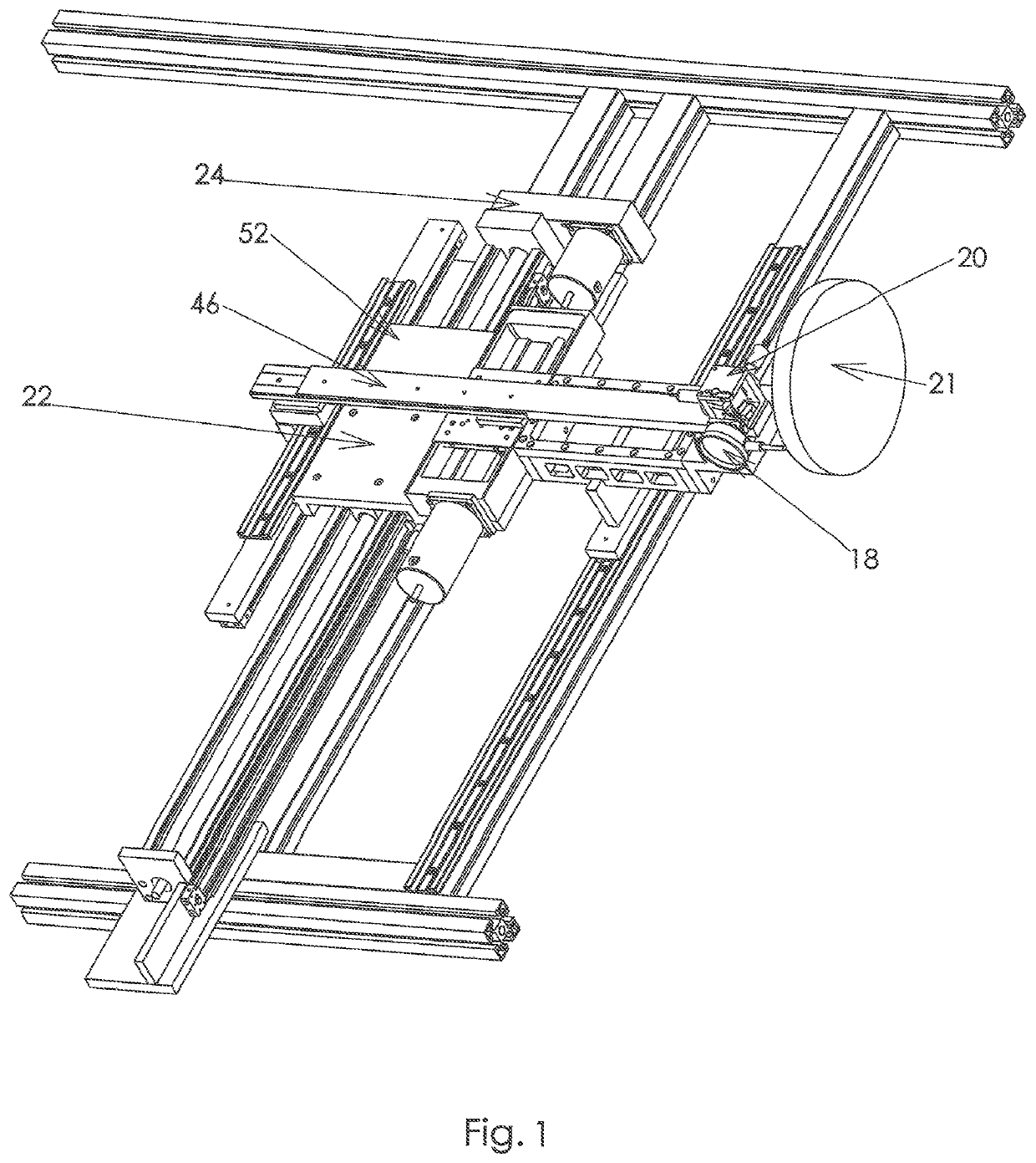
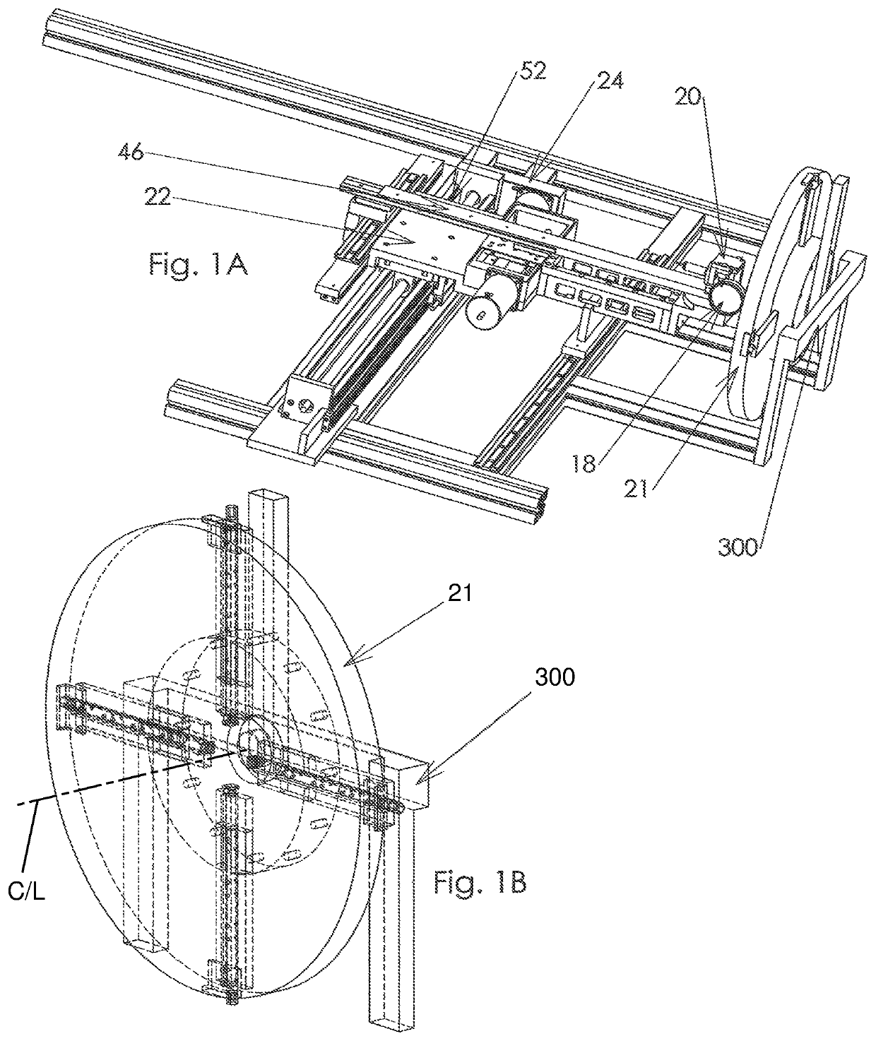
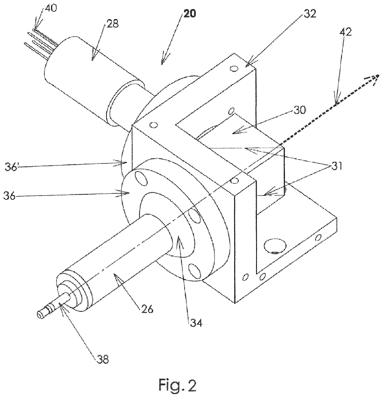
[0044]FIGS. 1 and 1A show an overall view of the invention. The X-unit 18 is simply a dial gauge, the extreme extension of which is a known offset from the emitter of the laser 26 (FIG. 2) in the laser head 20. In the position shown, it is used to ascertain the distance to a point on the optical surface under test (i.e., a lens or mirror surface), which is shown as item 21. The laser head 20 is mounted o...


PUM


Abstract

Systems and methods for testing and characterization of optical surfaces which works equally well on concave, flat, convex, and non-conic optical surfaces, and which does not require that a master surface be first produced. The method is automatic and requires little human intervention. It provides an extremely high degree of accuracy, and provides repeatability of measurements within a minuscule tolerance of error. The method determines the evolute of the surface automatically, deterministically, and repeatably via orthogonal reflection by ascertaining the evolute of the surface's figure along multiple diameters of the surface.

Description

FIELD OF THE INVENTION[0001]The present invention is directed to testing and characterization of optical surfaces, including concave, flat, convex, and non-conic optical or reflective surfaces. It does not require that a master surface be first produced.BACKGROUND OF THE INVENTION[0002]The Frenchman Leon Foucault in 1858 invented a method of testing concave optical surfaces using a pinhole, light source, and knife-edge. Refinements of this method permit characterization of such surfaces to a tolerance of about 1 / 10 wavelength of sodium light (the equivalent of two millionths of an inch) for optics having a focal ratio slower than about f / 2.0, and have permitted amateur telescope makers to construct excellent telescopes using very minimal tooling. The focal ratio, or f / number, is the focal length divided by the diameter of the surface. “Fast” means a low f / number (big fast lens on a camera might be an f / 1.5, small or slow lens, f / 8 or so). The faster a lens, the quicker the exposure ...

Claims


Application Information

Patent Timeline
Patent Type & Authority Patents(United States)
IPC IPC(8): G02B6/42G02B7/00
CPCG02B7/003G02B6/4221G02B6/425G01B9/10G01M11/005G01N2021/9511
Inventor KOKEN, TERRELL E
Owner KOKEN TERRELL E
Why Eureka
Try Eureka