Efficient class-G amplifier with wide output voltage swing

a technology of output voltage swing and amplifier, applied in the direction of gated amplifier, amplifier with semiconductor devices/discharge tubes, amplifiers with only semiconductor devices, etc., can solve the problem that the output stage associated with the next highest supply voltage may bear the complete burden, and achieve the effect of reducing nois

Inactive Publication Date: 2005-01-04
MICROCHIP TECH INC
View PDF11 Cites 119 Cited by
  • Summary
  • Abstract
  • Description
  • Claims
  • Application Information

AI Technical Summary

Benefits of technology

When the amplifier output voltage is above the lowest supply voltage the output stage associated with the next highest supply voltage may contribute all the current to the amplifier output. When the amplifier output rises to within delta V of the supply voltage for this output stage the output stage associated with the next highest supply voltage may begin to contribute current to the amplifier output. The transition regions in which two output stages whose supply voltages are adjacent share the current load of the amplifier may begin at delta V below each supply voltage. At this voltage, the output stage assoc...

Problems solved by technology

As the output voltage of the amplifier increases through delta V, the brunt of the amplifier output current may switch sources, so that by the tim...

Method used


Image

  • Efficient class-G amplifier with wide output voltage swing
  • Efficient class-G amplifier with wide output voltage swing
  • Efficient class-G amplifier with wide output voltage swing

Examples


Embodiment Construction

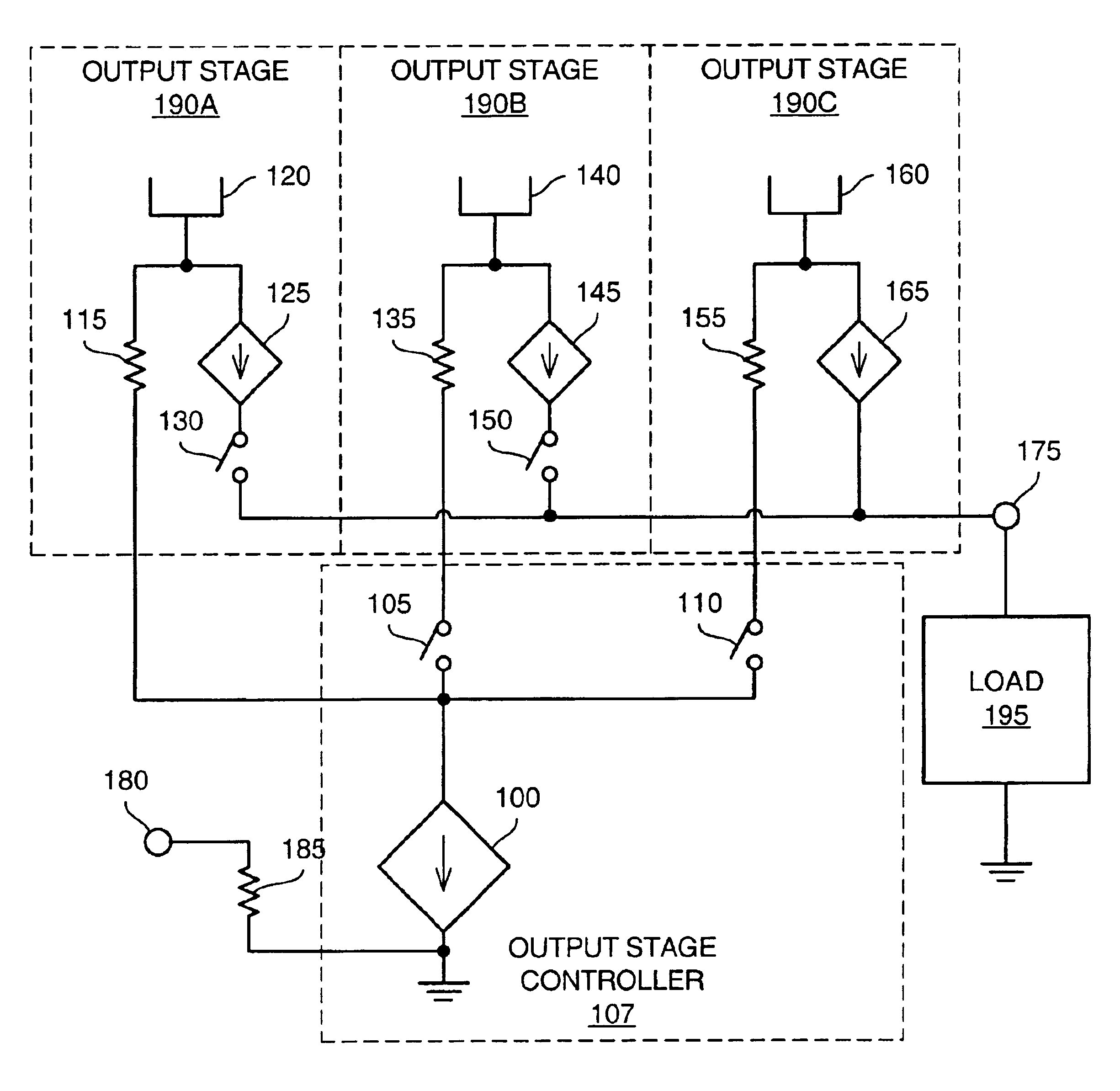
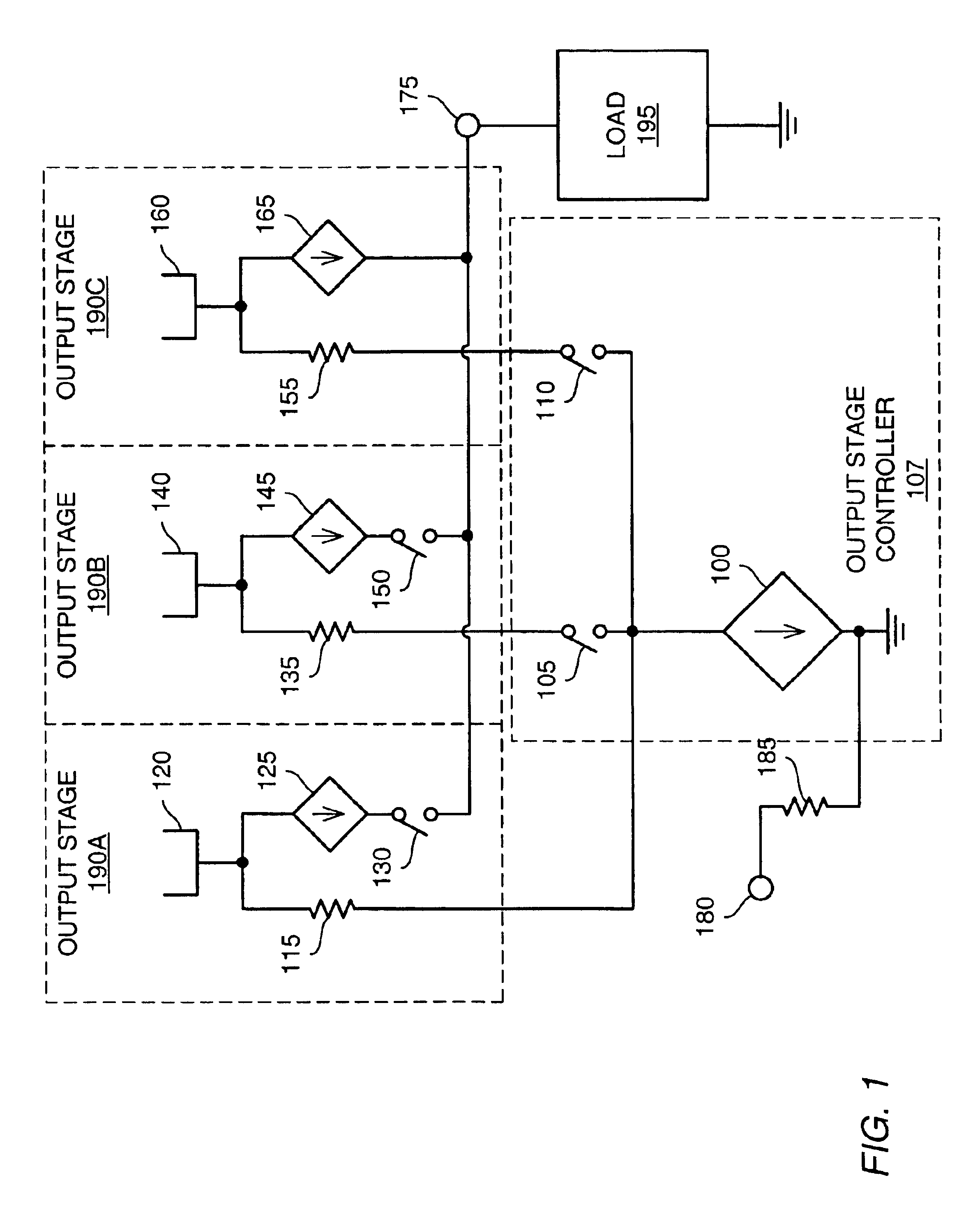
FIG. 1 shows a diagram of a class G amplifier, according to one embodiment. Voltage-controlled current sink 100 may draw current from the control sections of the output stages 190 in proportion to the amplifier input voltage 180. For example, output stage 190A may be associated with the lowest power supply voltage 120 of any output stage. When current sink 100 begins to draw current in response to input voltage 180, switches 105 and 110 associated with the control sections of output stages 190B and 190C respectively may be open. In this instance, all current drawn by current sink 100 may come from the control section of output stage 190A through resistor 115.

Current-controlled current source 125 may source current from the power supply of output stage 190A in proportion to the current through resistor 115. Switch 130 may be closed for amplifier output voltage 175 in the range of zero to the voltage 120 of the power supply associated with output stage 190A. Current source 125 may sup...


PUM


Abstract

Various embodiments of methods and apparatus for an amplifier with wide output voltage swing are disclosed. The amplifier may include multiple output stages, each associated with a distinct supply voltage. Each output stage may contribute current to the output of the amplifier over a range of amplifier output voltages and these ranges may overlap. Each output stage may contribute current until the amplifier output voltage reaches the supply voltage associated with that output stage. The amplifier output may be as great as the largest supply voltage minus a drop equal to Rdson for an output transistor multiplied by the output current. In a CMOS implementation, this voltage drop may be approximately 0.15V. When the amplifier output voltage is close to the supply voltage associated with an output stage, both that output stage and the output stage associated with the next highest supply voltage may contribute to the amplifier output.

Description

BACKGROUND OF THE INVENTION1. Field of the InventionThis invention relates to integrated circuits, and more particularly, to amplifiers implemented as integrated circuits.2. Description of the Related ArtThe basic function of an amplifier is to produce and output signal whose power is a multiple of the power of an input signal. In many applications it is desirable that the output waveform faithfully reproduce the shape of the input signal while magnifying its voltage and / or current in a linear fashion. Traditionally, amplifiers designed for these types of applications have been configured for class A operation.In an amplifier designed for class A operation, both output devices conduct continuously for the entire cycle of signal swing, or the bias current flows in the output devices at all times. The key ingredient of class A operation is that both devices are always on. There is no condition where one or the other is turned off. Because of this, class A amplifiers in reality are not...

Claims


Application Information

Patent Timeline
IPC IPC(8): H03F1/02H03F3/72H03F3/20H03F3/21
CPCH03F1/025H03F3/72H03F3/211
Inventor SOMERVILLE, THOMAS A.WORTEL, KLAAS
Owner MICROCHIP TECH INC
Why Eureka
Try Eureka