Optical element and optical pickup

a technology applied in the field of optical elements and optical pickups, can solve the problems of difficult to increase the thickness of the lens from a technique standpoint, difficult to produce a mold for use in sheet forming, and difficult to make both surfaces of the lens aspherical surfaces, so as to reduce the comatic aberration

Inactive Publication Date: 2005-01-04
SONY CORP
View PDF2 Cites 2 Cited by
  • Summary
  • Abstract
  • Description
  • Claims
  • Application Information

AI Technical Summary

Benefits of technology

In view of the aforesaid aspect, it is an object of the present invention to provide an optical element in which a diameter of lens can be reduced, a radius of curvature of lens can be increased and a comatic aberration produced when an optical axis of incident light is inclined relative to a lens can be corrected.
Consequently, it becomes possible to decrease a comatic aberration produced when the optical axis of incident light is inclined relative to the lens.
According to the arrangement of the above-mentioned optical pickup of the present invention, since the optical pickup includes the above-mentioned optical element of the present invention, a comatic aberration produced when the optical axis of the incident light is inclined relative to the lens can be decreased. Hence, it becomes possible to form spots of satisfactory shape on a recording medium by focusing incident light.

Problems solved by technology

However, in order to manufacture a lens with a small diameter and of which the radius of curvature is large, it becomes difficult to produce a mold for use in sheet forming.
However, according to these previously-proposed manufacturing methods, it is very difficult to make both surfaces of a lens become aspherical surfaces and it is also very difficult to increase a thickness of a lens from a technique standpoint.
In this lens shaped like the flat convex aspherical lens, if such lens is designed such that spherical aberration produced on the optical axis on the major surface side that is the aspherical surface may be corrected, there then arises a problem that an amount of comatic aberration produced when the optical axis of incident light is inclined relative to the lens will not be decreased at the same time.

Method used


Image

  • Optical element and optical pickup
  • Optical element and optical pickup
  • Optical element and optical pickup

Examples


example 1

DESIGN EXAMPLE 1

Specific design examples of the optical elements according to the present invention will be described below.

There is prepared an optical element 25. FIG. 9 is a schematic cross-sectional view showing an arrangement of such optical element 25.

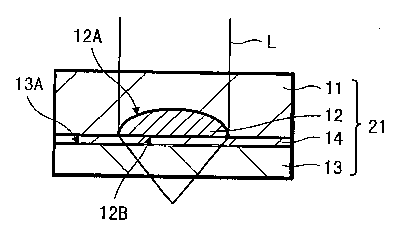
Specifically, there is prepared the optical element 25 in which the lens 12 serving as the flat convex aspherical lens whose entrance end face 12A is formed as the aspherical surface and of which the exit end face 12B is shaped as the flat surface similarly to the optical element 21 shown in FIG. 1 is embedded into the lens base plate 11 and in which the aberration correction base plate 13 is attached to the lens base plate 11.

In this optical element 25, the aberration correction base plate 13 is formed thick as compared with the lens base plate 11.

An air layer 17 is located on the image point side of the aberration correction base plate 13 of this optical element 25.

First, the numerical aperture NA of the lens 12 of the optical ...

example 2

DESIGN EXAMPLE 2

There is prepared an optical element 26. FIG. 12 is a schematic cross-sectional view showing an arrangement of such optical element 26.

Specifically, there is prepared the optical element 26 in which the lens 12 serving as the flat convex aspherical lens whose entrance end face 12A is formed as the aspherical surface and of which the exit end face 12B is shaped as the flat surface similarly to the optical element 21 shown in FIG. 1 is embedded into the lens base plate 11 and in which the aberration correction base plate 13 is attached to the lens base plate 11.

In this optical element 26, the aberration correction base plate 13 is formed slightly thin as compared with the lens base plate 11.

This optical element 26 constructs the slider similarly to the arrangement shown in FIG. 5, and has the thin air layer 17 disposed between it and the image point side of the aberration correction base plate 13, i.e. an optical disk substrate 8 of the optical disk 10. In FIG. 12, ref...


PUM

PropertyMeasurementUnit
refractive indexaaaaaaaaaa
transparentaaaaaaaaaa
thicknessaaaaaaaaaa

Abstract

The system and methods of the present invention are directed to an optical pickup. The optical includes at least a light source, a lens for focusing and irradiating light from the light source on a recording medium, and an optical pickup element. The optical pickup element includes a lens base plate in which a lens made of a material having a high refractive index is embedded within a transparent base plate to pass incident light. The optical element further includes an aberration correction base plate formed of a transparent parallel flat plate-like base plate to pass light and correcting a comatic aberration produced on the lens. The lens base plate and the aberration correction base plate are integrated such that the lens base plate and the aberration correction base plate are parallel to each other. Moreover, the aberration correction base plate is located on the side of a point at which incident light is focused by the lens.. The optical element can reduce the diameter of the lens, increase the radius of curvature of the lens, and correct a comatic aberration produced when an optical axis of incident light is inclined relative to the lens.

Description

BACKGROUND OF THE INVENTION1. Field of the InventionThe present invention relates to an optical element including a lens base plate in which a lens of a high refractive index is embedded into a base plate and an optical pickup using this optical element.2. Description of the Related ArtIn recent years, micro-lenses are widely used in various fields, such as optical communication and an optical head of an optical pickup for use in recording and reproducing an information signal on and from an optical recording medium, e.g., optical disk. It is strongly requested that these micro-lenses should have a large NA (numerical aperture) and should be formed as aspherical micro-lenses.In micro-lenses for use in optical communication, an optical pickup and the like, a sheet forming method using a mold has hitherto been used as a manufacturing method for mass-producing micro-lenses inexpensively.When micro-lenses are used in the field of optical pickup and so on, there is an increasing demand o...

Claims


Application Information

Patent Timeline
Patent Type & Authority Patents(United States)
IPC IPC(8): G02B13/18G02B27/00G02B7/02G11B7/135G02B13/00G02B3/00G11B7/1365G11B7/1374G11B7/1392
CPCG02B7/025G02B13/18G11B7/13922G11B7/1365G11B7/1374G02B27/0025
Inventor MIURA, TAKAHIROYAMADA, MASAHIRO
Owner SONY CORP
Why Eureka
Try Eureka