Two-step ripple-free multi-phase buck converter and method thereof

a multi-phase buck converter and ripple-free technology, applied in the direction of electric variable regulation, process and machine control, instruments, etc., can solve the problems of poor conversion efficiency and disadvantageous ripple output of the converter, and achieve the effect of improving conversion efficiency

Inactive Publication Date: 2005-01-04
RICHTEK TECH
View PDF6 Cites 68 Cited by
  • Summary
  • Abstract
  • Description
  • Claims
  • Application Information

AI Technical Summary

Benefits of technology

Yet further object of the present invention is to provide a multi-phase buck converter with improved conversion efficiency.

Problems solved by technology

Unfortunately, the rippled output is disadvantageous to the load of the converter.
Further, the more is the difference between the input voltage VIN and the converter output voltage VOUT, the poorer efficiency has the converter.

Method used


Image

  • Two-step ripple-free multi-phase buck converter and method thereof
  • Two-step ripple-free multi-phase buck converter and method thereof
  • Two-step ripple-free multi-phase buck converter and method thereof

Examples


Embodiment Construction

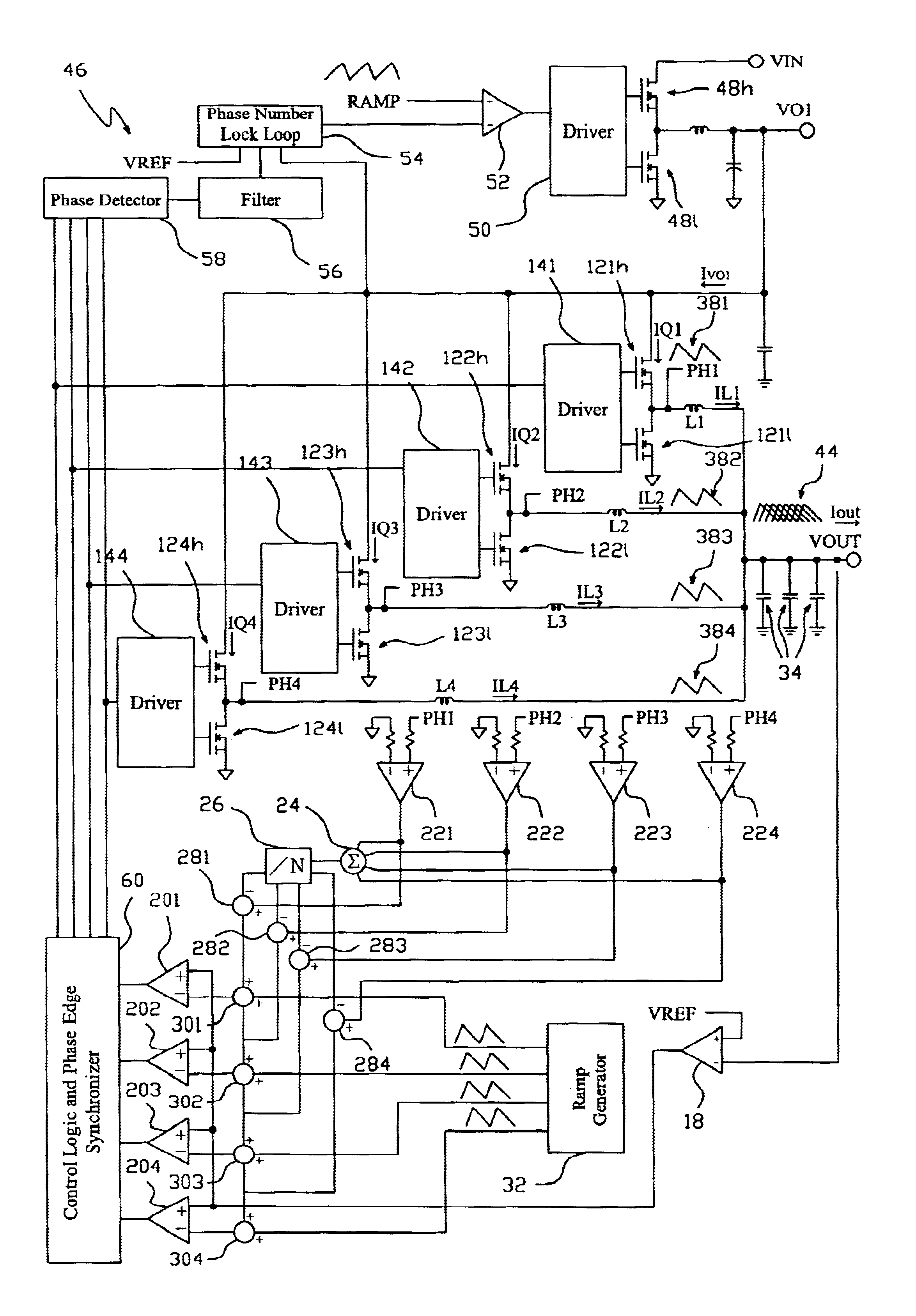
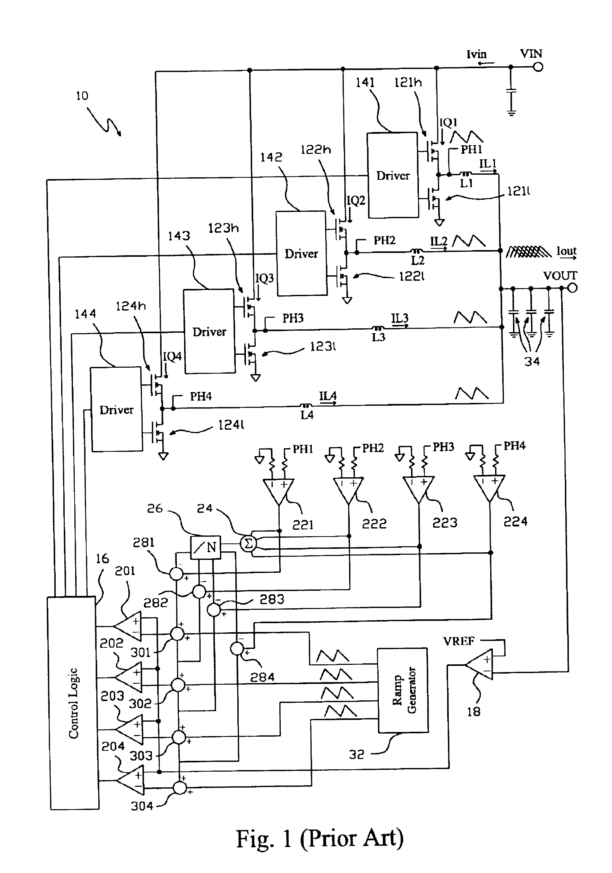
FIG. 4 is a four-phase converter 46 according to the present invention, which comprises a first-stage voltage regulator and a second-stage voltage regulator. The first-stage voltage regulator includes an output stage composed of MOSFETs 48h and 48l connected in series, a driver 50 to switch the MOSFETs 48h and 48l, a pulse width modulator 52 to produce the PWM signal to switch the driver 50. Moreover, a phase number lock loop 54, a filter 56, a phase detector 58, and a phase edge synchronizer 60 are provided. The second-stage voltage regulator is similar to the conventional circuit shown in FIG. 1, except that the control logic and phase edge synchronizer 60 are integrated in a block, and the same reference numbers are used to refer to the same blocks as in FIG. 1. The MOSFET 48h of the first-stage voltage regulator is connected with the supply voltage VIN and through which the input voltage VIN is converted to an ideal intermediate voltage VO1. The intermediate voltage VO1 is then ...


PUM


Abstract

A two-step ripple-free multi-phase buck converter and method thereof comprises a first-stage voltage regulator to convert an input voltage to an intermediate voltage and a second-stage voltage regulator with a phase number not less than two to further convert the intermediate voltage to an output voltage by a split phase control, in which the ratio of the intermediate voltage to the output voltage is intended to the phase number such that the steady state output current of the converter approaches to be ripple-free, and hence the drivers and MOSFETs for the second-stage voltage regulator are lower cost, the efficiency of the second-stage voltage regulator is improved, and a higher slew rate current is obtained for transient driving capabilities.

Description

FIELD OF THE INVENTIONThe present invention relates generally to a multi-phase buck converter, and more particularly to a two-step ripple-free multi-phase buck converter and the method thereof.BACKGROUND OF THE INVENTIONMulti-phase buck converters have been widely used for various applications, such as power supply circuits. For example, as shown in FIG. 1, a four-phase buck converter 10 has four output stages each corresponding to one phase thereof and including a pair of MOSFETs connected in series, i.e., MOSFETs 121h and 121l, 122h and 122l, 123h and 123l, and 124h and 124l, manipulated by respective drivers 141, 142, 143 and 144 in respective phases, which are controlled by a control logic 16. To obtain stable and balanced output in each phase, an error amplifier 18 is employed to compare a reference voltage VREF with the output voltage VOUT of the converter 10 to thereby produce a voltage error signal supplied to four pulse width modulation (PWM) comparators 201, 202, 203 and 2...

Claims


Application Information

Patent Timeline
Patent Type & Authority Patents(United States)
IPC IPC(8): H02M3/158H02M3/04
CPCH02M3/1584H02M2001/0029H02M1/0029
Inventor TAI, LIANG-PINHSIEH, SHWU-LIANGWANG, HUNG-ILIU, JING-MENG
Owner RICHTEK TECH
Why Eureka
Try Eureka