
Fixing device

a fixing device and peeling technology, applied in the field of image forming apparatus, can solve the problems of adhesion to the surface, fuser roller scratching, constant gap between the end of the peeling member and the pressure roller, etc., and achieve the effect of improving the peeling performan

Inactive Publication Date: 2005-01-04
SEIKO EPSON CORP
View PDF4 Cites 16 Cited by
  • Summary
  • Abstract
  • Description
  • Claims
  • Application Information

AI Technical Summary

Benefits of technology

The present invention has been made in order to solve the aforementioned conventional problems. The first object of the present invention is to provide a fixing device which can achieve improved peeling performance of peeling off a recording medium from a fuser roller and a pressure roller.
The second object of the present invention is to provide a fixing device which can achieve improved peeling performance of peeling of f a recording medium from a fuser roller and a pressure roller and can prevent the occurrence of linear defects on image.
The third object of the present invention is to provide a fixing device which can achieve increased durability of a peeling member and can improve the quality of fixed image. For achieving the aforementioned object, the fixing device of the present invention is characterized in that the peeling member comprises a substrate having an edge at the end thereof and a fluoro resin layer formed on the surface of the substrate.

Problems solved by technology

However, even if such a fuser roller is used, the fused toner easily adheres to the surface of the fuser roller because it is soft and highly viscous, and the sheet may wind around the fuser roller.
In the aforementioned conventional fixing device, however, since the peeling member is in contact with the fuser roller, there is a problem that the fuser roller may be scratched.
However, this method has a problem that a gap between the end of the peeling member and the fuser roller must be held always constant over the entire length in the axial direction of the fuser roller in order to peel off a recording medium from the fuser roller with constant force over the entire width of the recording medium.
In case of dual-side printing, there is also a problem that toner on the pressure roller side corresponding to locations where no toner is transferred on the fuser roller is fused so that the recording medium easily winds around the pressure roller.
However, similarly to the peeling member on the fuser roller side, there is a problem that a gap between the end of the peeling member and the pressure roller must be held always constant.
If the contact angle of the peeling member relative to the recording medium is not good, the peeling performance of recording media should be poor and linear defects may be created on image.
In the conventional fixing device, the peeling member is in contact with the fuser roller, so there is a problem that the fuser roller may be scratched.
Therefore, it is very difficult to control the gap between the peeling member and the surface of the fuser roller.

Method used


Image

  • Fixing device
  • Fixing device
  • Fixing device

Examples


example 1

Fuser RollerDiameter: 30 mm,Elastic layer: silicone rubber (JIS-A hardness: 5°) with a thickness of 1 mm,Outer layer: PFA (tetrafluoroethylene / perfluoroalkyl vinyl ether copolymer) with a thickness of 40 μm, with a built-in heater.

Pressure RollerDiameter: 35 mm,Elastic layer: silicone rubber (JIS-A hardness: 10°) with a thickness of 6 mm,Outer layer: PFA with a thickness of 40 μm.

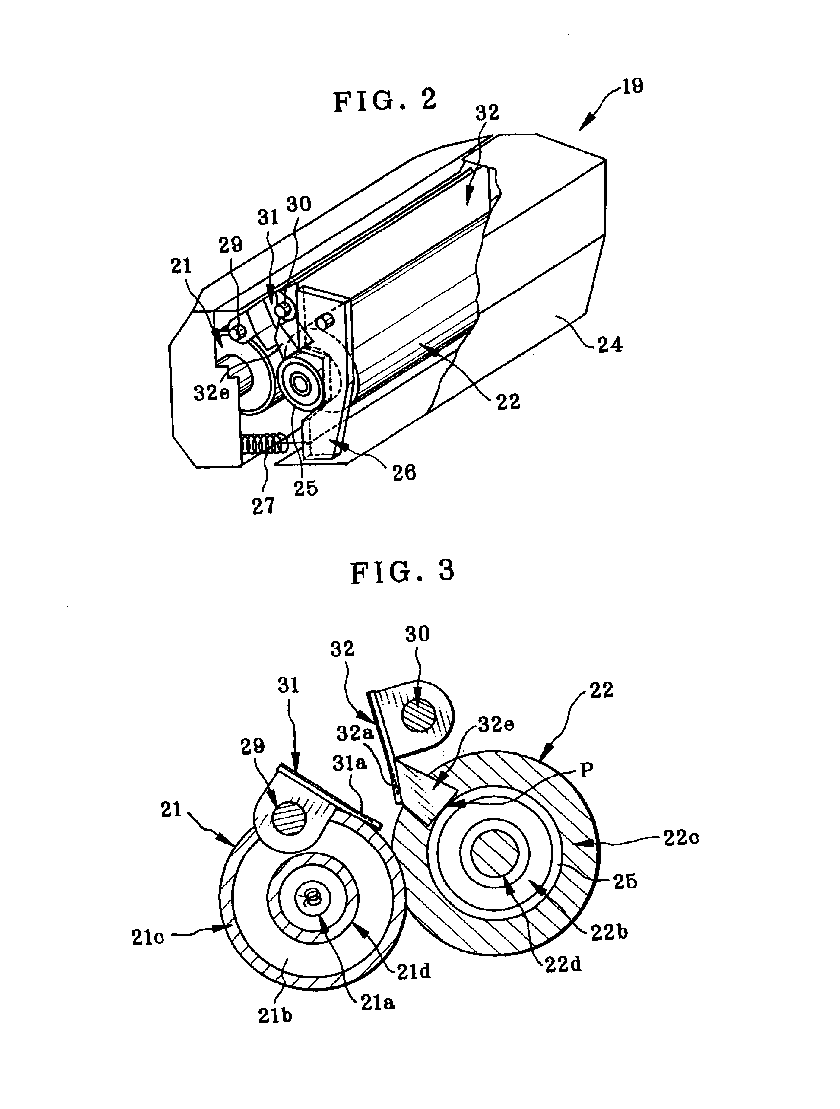
Distance between the outlet of the fixing nip and the end of the peeling portion 31a: 6.5 mm, Width of the fixing nip: 8 mm, Fusing Temperature: 185° C., Sheet feeing speed: 215 mm / s, Pressure load on the rollers: 31 kgf.

example 2

Fuser RollerDiameter: 40 mm,Elastic layer: silicone rubber (JIS-A hardness: 8°) with a thickness of 1.5 mm,Outer layer: PFA with a thickness of 40 μm,Built-in heater.

Pressure RollerDiameter: 50 mm,Elastic layer: silicone rubber (JIS-A hardness: 10°) with a thickness of 6 mm,Outer layer: PFA with a thickness of 40 μm.

Distance between the outlet of the fixing nip and the end of the peeling portion 31a: 6.5 mm, Width of the fixing nip: 8 mm, Fusing Temperature: 185° C., Sheet feeing speed: 215 mm / s, Pressure load on the rollers: 26 kgf.

example 3

Fuser RollerDiameter: 30 mm,Elastic layer: silicone rubber (JIS-A hardness: 5°) with a thickness of 1 mm,Outer layer: PFA with a thickness of 40 μm,Built-in heater.

Pressure RollerDiameter: 35 mm,Elastic layer: silicone rubber (JIS-A hardness: 10°) with a thickness of 6 mm,Outer layer: PFA with a thickness of 40 μm.

Distance between the outlet of the fixing nip and the end of the peeling portion 31a: 7.5 mm, Width of the fixing nip: 8 mm, Fusing Temperature: 185° C., Sheet feeing speed: 215 mm / s, Pressure load on the rollers: 31 kgf.

Evaluation items

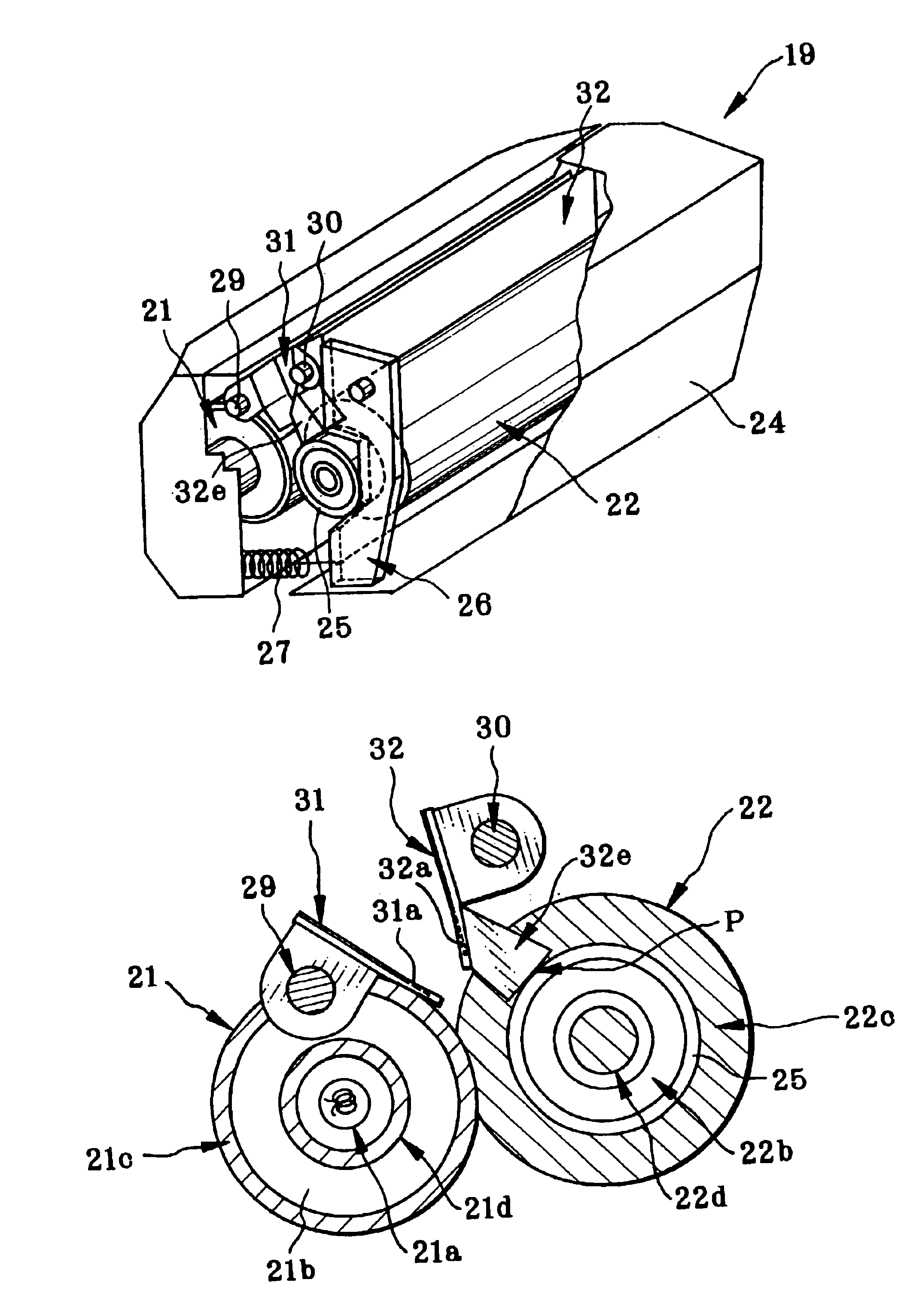
(1) Linear defects on image: a full solid image was printed and “linear defects” as scratch marks by the peeling portion 31a were visually observed and evaluated.

∘: no linear defectsΔ: minor light linear defectsX: deep and severe linear defects

(2) Peeling performance: a full solid image was successively printed on 250 sheets of paper and the number of failures of feeding operation of the fixing device was counted.⊚: no failure∘: one or two ...


PUM


Abstract

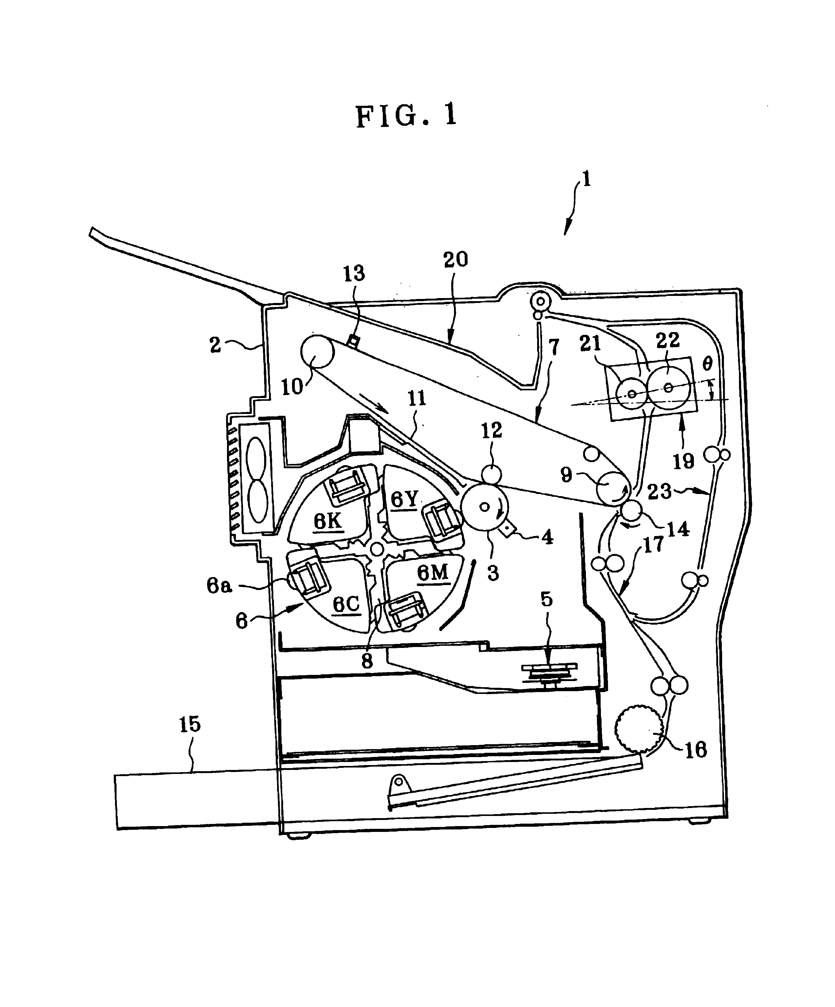
In order to improve the peeling performance for peeling off a recording medium from a fuser roller and a pressure roller, peeling members 31, 32 are provided which are arranged on the downstream side in the recording medium feeding direction relative to a fixing nip portion to extend in the axial direction of the fuser roller 21 and the pressure roller 22 and are disposed in proximity to the fuser roller and the pressure roller, respectively. The positioning of the peeling member 31 for the fuser roller is conducted on the surface of the fuser roller, and the positioning of the peeling member 32 for the pressure roller is conducted on surfaces of bearings 25 for the pressure roller.

Description

BACKGROUND OF THE INVENTIONThe present invention relates to an image forming apparatus utilizing electrophotographic technology such as a copying machine, a printer, and a facsimile machine and, more particularly, to a fixing device provided with a peeling member for peeling a recording medium fed out of a fixing nip portion.Widely used as a fixing device for fixing a toner image transferred onto a recording medium such as a paper sheet in an image forming apparatus utilizing electrophotographic technology is a fixing device in which a sheet with a toner image transferred thereto is passed through a nip portion between a pair of rollers consisting of a fuser roller and a pressure roller to thereby fuse the toner image to the sheet by means of heating by the fuser roller and compression by the two rollers.Generally, in the fixing device of this type, since the toner image fused to the sheet comes into contact with the fuser roller, a roller having a surface coated with a fluoro resin...

Claims


Application Information

Patent Timeline
Patent Type & Authority Patents(United States)
IPC IPC(8): G03G15/20
CPCG03G15/2028
Inventor MOURI, SYUHEIFUJISAWA, KAZUTOSHITAJJIMA, TAKESHITAKEHANA, HIROSHI
Owner SEIKO EPSON CORP
Learn More