On-line rotating equipment monitoring device

Inactive Publication Date: 2005-01-04
COMPUTATIONAL SYST
View PDF69 Cites 66 Cited by
  • Summary
  • Abstract
  • Description
  • Claims
  • Application Information

AI Technical Summary

Benefits of technology

This rotating equipment monitoring device provides the advantage of operating on-line, in a dedicated manner to collect and process data for a particular piece of rotating equipment within the plant and to provide immediate indications of the current or future operating state of that equipment to plant personnel via plant communication infrastructure. Because the monitoring device is connected to and capable of performing diagnostics

Problems solved by technology

However, because monitoring of this equipment is not typically needed for process control, this equipment, if monitored at all, is generally monitored very infrequently, such as on a monthly basis, and only for maintenance purposes.
Unfortunately, in both of these instances, there may be a significant time lag between the times at which the rotating equipment data is collected and, additionally, there may be a further time lag between the time when the data is collected and when a diagnostic report is received at the plant.
As a result, there are significant periods of times during which problems with the ro

Method used


Image

  • On-line rotating equipment monitoring device
  • On-line rotating equipment monitoring device
  • On-line rotating equipment monitoring device

Examples


Example

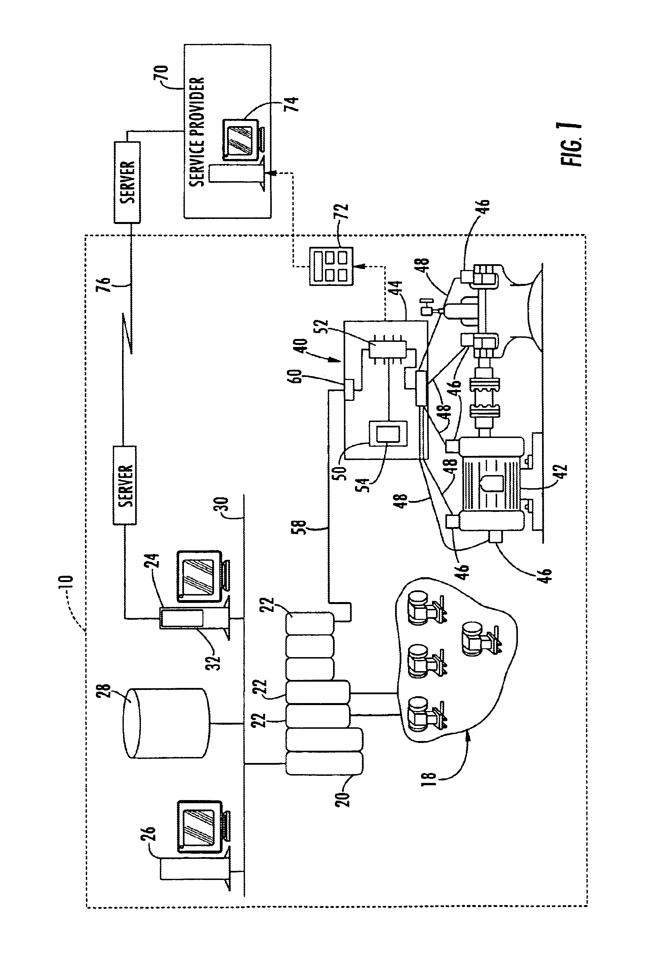
Referring now to FIG. 1, a process plant 10 includes numerous field devices 18 connected to a distributed control system (DCS) controller 20 via one or more input / output devices 22. The DCS controller 20 is connected to one or more host computers 24 and 26 and to a data historian 28 via a bus 30 which may be, for example, an Ethernet bus. As is known, the DCS controller 20 performs any desired type of control within the plant 10 by sending signals to and receiving signals from the field devices 18 and processing such signals using any known or standard control software. The DCS controller 20 may report status information to one or more applications within, for example, the host computer 24 regarding the operating state of the process and / or the operating state of the field devices 18. If desired, one of the applications 32 within the host computer 24 may be a maintenance application, such as the AMS application described above, which tracks the operating state of different devices w...


PUM


Abstract

A rotating equipment monitoring device includes a set of sensors, such as temperature, speed, pressure, and vibration sensors, locally connected to a diagnostic unit having a plant communication interface and a processor that implements one or more diagnostic routines. The diagnostic unit collects data from the sensors and performs diagnostics thereon to detect actual or potential problems with the rotating equipment on a continuous or semi-continuous basis. Using the communication interface, the diagnostic unit automatically sends signals indicating detected conditions of the rotating equipment to a maintenance system or a control system via standard or common communication network, such as a HART or Fieldbus network. The diagnostic unit may also be intermittently coupled to an off-line computer, such a one associated with a service provider, who may verify or further define the diagnostics provided by the diagnostic unit.

Description

FIELD OF THE TECHNOLOGYThe present invention relates generally to process plant monitoring devices and, more particularly, to a device that performs on-line monitoring for rotating equipment within a process plant.DESCRIPTION OF THE RELATED ARTProcess control systems, like those used in chemical, petroleum or other processes, typically include one or more centralized or decentralized process controllers communicatively coupled to at least one host or operator workstation and to one or more process control and instrumentation devices, such as field devices, via analog, digital or combined analog / digital buses. Field devices, which may be, for example valves, valve positioners, switches, transmitters, and sensors (e.g., temperature, pressure and flow rate sensors), perform functions within the process such as opening or closing valves and measuring process parameters. The process controller receives signals indicative of process measurements or process variables made by or associated ...

Claims


Application Information

Patent Timeline
IPC IPC(8): G05B23/02
CPCG05B23/0262G05B23/0229
Inventor ERYUREK, EVRENBOUSE, KAIREEVES, TODD
Owner COMPUTATIONAL SYST
Why Eureka
Try Eureka