Electromechanical valve assembly for an internal combustion engine

a technology of electromechanical valves and internal combustion engines, applied in the direction of non-mechanical valves, machines/engines, operating means/releasing devices of valves, etc., can solve the problems of inability to effectively increase fuel efficiency and reduce emissions in engines, the electromechanical valve energy requirement is reduced, and the fuel efficiency is increased.

Inactive Publication Date: 2005-01-11
FORD GLOBAL TECH LLC
View PDF30 Cites 24 Cited by
  • Summary
  • Abstract
  • Description
  • Claims
  • Application Information

AI Technical Summary

Benefits of technology

A method for current recirculation (i.e., energy recovery) in electromechanical valve assemblies disposed in an internal combustion engine is also provided. The current recirculation methodology is a regenerative method that reduces the energy requirement of electromechanical valves during actuation of the valves. The method includes providing a first electromechanical valve assembly having first and second stator phases selectively connected between a first node and ground. The method further includes providing a second electromechanical valve assembly having third and fourth stator phases selectively connected between the first node and ground. The method further includes generating a braking current in the first and second stator phases of the first electromechanical valve assembly. Finally, the method includes connecting the third and fourth stator phases of the second electromechanical valve assembly to the first node to direct the braking current into the third and fourth stator phases as an accelerating current.
The electromechanical valve assembly and the control system related thereto, represent a significant improvement over conventional valve assemblies and control systems. In particular, the inventive valve assembly and control system enable the precise control of a valve dwell time, a valve opening rate, a valve closing rate, a valve dwell position, and valve phasing. As a result, the inventive valve assembly allows for increased fuel efficiency and lower emissions in an engine as compared with conventional valve assemblies. Further, the position of the valve head may be accurately controlled for soft seating with a valve seat—resulting in reduced engine noise. Still further, the valve assembly may be packaged in a relatively small package volume allowing automotive designers increased flexibility in placement of the engine. Finally, the inventive method of current recirculation provides for decreased electrical energy consumption by the inventive valve assembly as compared with conventional electromechanical valve assemblies.

Problems solved by technology

In particular, the valve assembly 14 cannot precisely control a valve dwell time duration, a valve dwell position, a valve opening rate, a valve closing rate, valve phasing.
Thus, the valve assembly 14 cannot be utilized to effectively increase fuel efficiency and lower emissions in an engine.
Further, the valve assembly 14 does not provide for soft seating of the valve head 30 on the valve seat 32 under all operating conditions of the engine including temperature extremes and control strategy variations.
As a result, the valve head 30 generates undesirable noise when contacting the valve seat 32.
However, the known valve assembly suffers from several disadvantages.
First, the valve assembly requires a separate cam resulting in increased component and manufacturing costs.
Further, the valve assembly requires a relatively large package space since a separate cam is utilized for each poppet valve.

Method used


Image

  • Electromechanical valve assembly for an internal combustion engine
  • Electromechanical valve assembly for an internal combustion engine
  • Electromechanical valve assembly for an internal combustion engine

Examples


Embodiment Construction

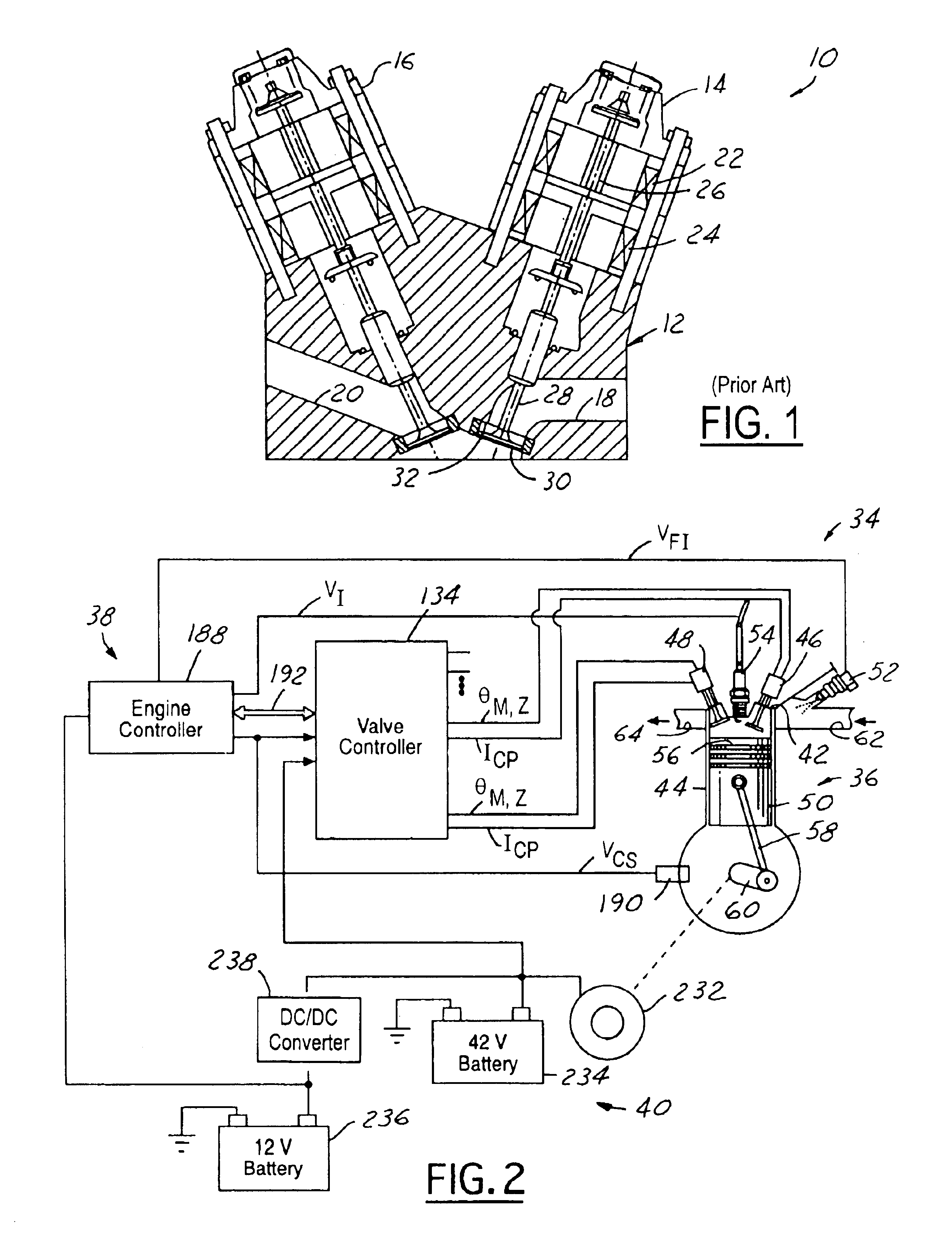
Referring now to the drawings wherein like reference numerals are used to identify identical components in the various views, FIG. 2 illustrates an automotive vehicle 34 having an engine 36, an engine control system 38, and a power distribution system 40.

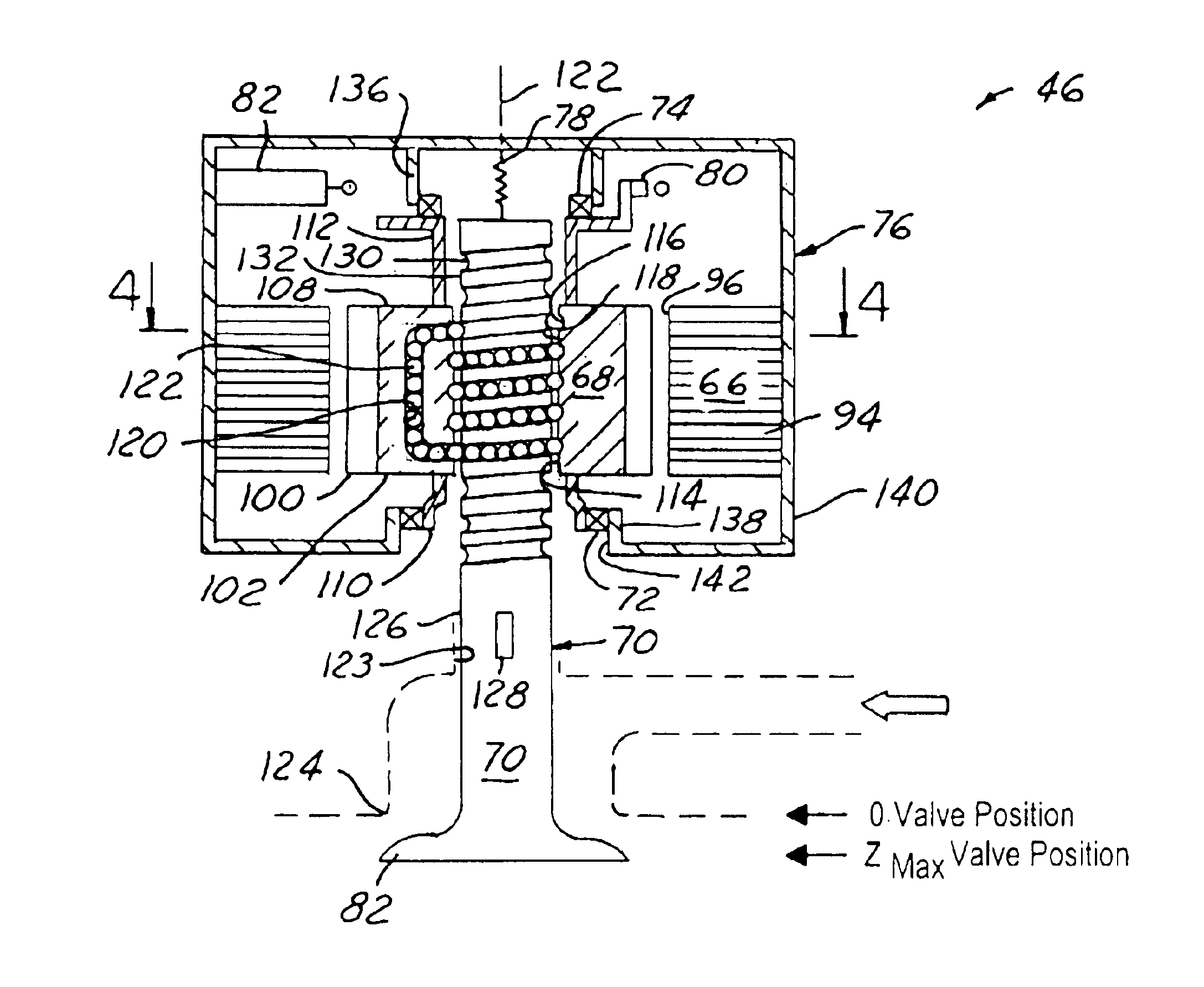
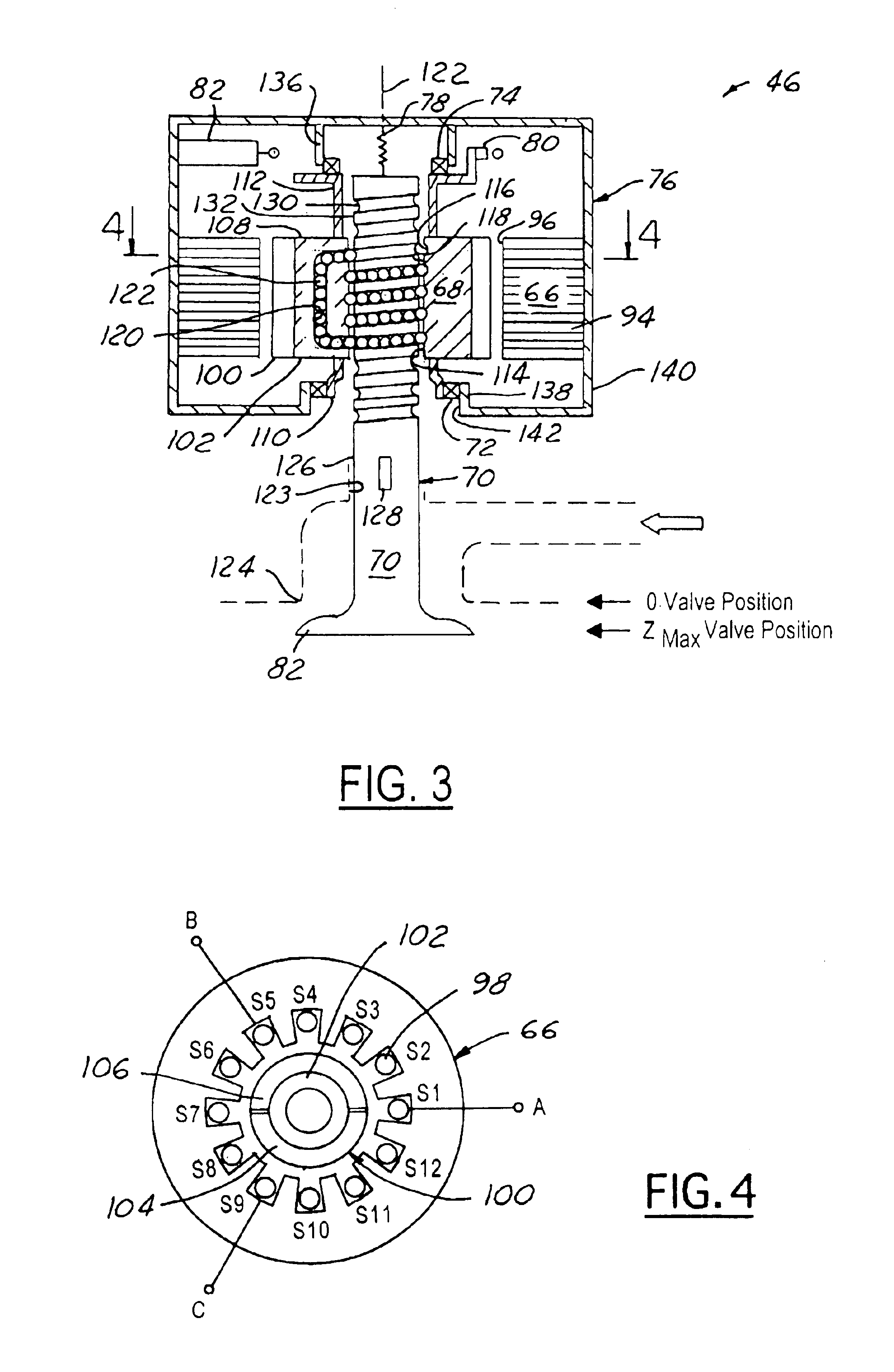
The engine 36 comprises an internal combustion engine. The engine 36 includes an engine head 42, an engine block 44, electromechanical valve assemblies 46, 48, a cylinder 50, a fuel injector 52, a spark plug 54, a piston 56, a connecting rod 58, and a crankshaft 60. Even though one cylinder 50 is shown in FIG. 2 for purposes of clarity, the engine 36 includes a plurality of cylinders 50, each cylinder 50 having valve assemblies 46, 48, fuel injector 52, spark plug 54, piston 56, and connecting rod 58.

The engine head 42 is conventional in the art and defines an intake line 62 and a exhaust line 64. The engine head 42 is mounted to the engine block 44 and is configured to hold the valve assemblies 46, 48, the spark plug 54, and the fu...


PUM


Abstract

An electromechanical valve assembly 46 for an internal combustion engine 36 is provided. The valve assembly 46 includes a rotor 68 centered about a first axis 122 having a bore 114 extending generally axially therethrough. The valve assembly 46 further includes a stator 66 operatively disposed about the rotor 68 for producing a torque to cause rotation of the rotor 68 about the axis 122. Finally, the valve assembly 46 includes a valve 70 having a valve stem 126 and a valve head 84 The valve stem 126 extends generally axially through the bore 114 of the rotor 68. The valve stem 126 is also configured to move generally axially responsive to the rotation of the rotor 68 to selectively engage and disengage the valve head 84 with a valve seat 124 of the engine 36.

Description

FIELD OF THE INVENTIONThis invention relates to an engine valve assembly, and particularly, to an electromechanical valve assembly for an internal combustion engine.BACKGROUND OF THE INVENTIONAutomotive manufacturers are currently utilizing camless intake and exhaust valve assemblies to control fluid communication in engine cylinders of internal combustion engines. The camless valve assemblies may utilize hydraulic, pneumatic, or electromechanical means to move a valve.It is further known that varying an engine valve dwell time (i.e., the time interval a valve is open), a valve dwell position (i.e., the amount the valve is open), a valve opening rate, a valve closing rate, and an initial opening time of a valve (i.e., valve phasing) may be used to increase fuel efficiency and lower emissions. Further, the most flexible valve assemblies may be independently actuated / controlled with respect to other valve assemblies in an engine.Referring to FIG. 1, a known engine 10 having an engine ...

Claims


Application Information

Patent Timeline
Patent Type & Authority Patents(United States)
IPC IPC(8): F01L9/04F01L3/24F01L9/20F16K31/04
CPCF01L9/04F01L2009/0486F01L2009/4086F01L9/20
Inventor MILLER, JOHN MICHAEL
Owner FORD GLOBAL TECH LLC
Why Eureka
Try Eureka