Wing structure of air swirling device for internal combustion engine

Inactive Publication Date: 2005-01-11
KIM SEI YOUNG
View PDF12 Cites 22 Cited by
  • Summary
  • Abstract
  • Description
  • Claims
  • Application Information

AI Technical Summary

Benefits of technology

Each of the wings has at least one or more air flow holes formed at prescribed positions for reducing air flow resistance due to eddy generation at the negative pressure zone of the wing.
The wave surfaces formed on the wings of the swirling device of the present inventio

Problems solved by technology

The prior art has the disadvantage that the air resistance generated when the air flow is rotated cannot be completely prevented.
However, such a device exhibits a high amount of friction resulting in a reduced amount of inlet air and thus is used only for a gasoline engine of the carburetor type.
However, such a device has various disadvantages, such as for example, reduced output of the engine due to a reduced quantity of inlet air and a loss of fuel because of the eddies generated at the rear surface (negative pressure zone) of the wings when the air flow is swirled.
However, the slits 12 formed in the wings 11 of the conventional swirling device of the in

Method used


Image

  • Wing structure of air swirling device for internal combustion engine
  • Wing structure of air swirling device for internal combustion engine
  • Wing structure of air swirling device for internal combustion engine

Examples


Embodiment Construction

Reference will now be made in detail to the preferred embodiments of the present invention, examples of which are illustrated in the accompany drawings.

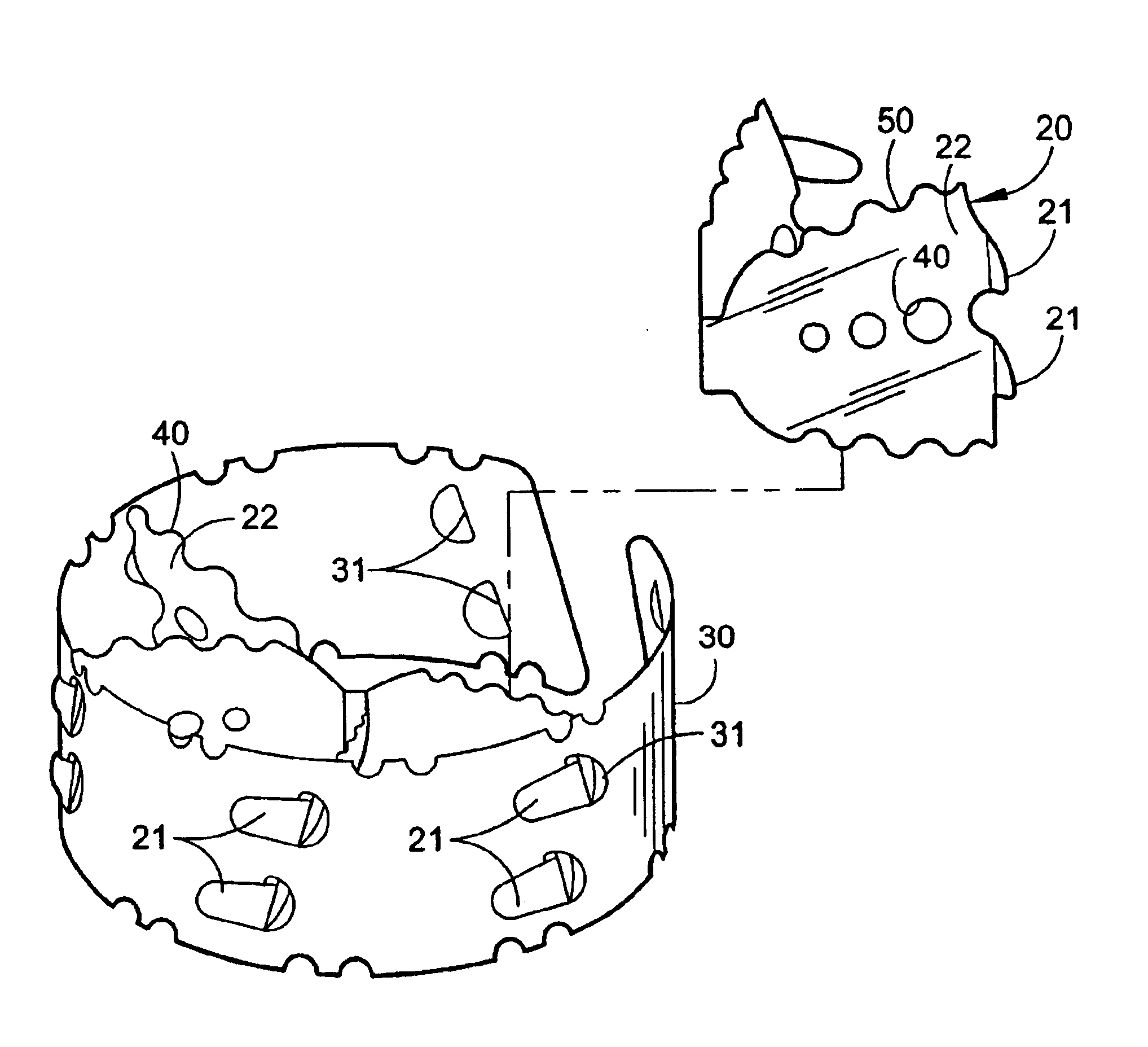
FIGS. 3-7 show various examples of wings of the swirling device of an internal combustion engine according to the present invention. FIG. 3 is a partially exploded perspective view of wings 20 coupled to a swirling device body 30; FIG. 4 is a plan view of the wings 20 assembled together with the swirling device body 30; FIGS. 5(A)-5(D) show various examples of shapes and arrangements of air flow holes 40 of the wings 20 of the present invention, wherein FIG. 5(A) is an example of a regular arrangement, FIG. 5(B) is an example of an independent arrangement, FIG. 5(C) is an example of a cross arrangement, and FIG. 5(D) is an example of a multiple arrangement.

A plurality of the wings 20 of the swirling device of the internal combustion engine according toe the present invention, as shown in FIG. 3, are mounted slantingly and radially on...


PUM


Abstract

An air swirling device adapted to be used in the air flow system of an internal combustion engine which comprises a swirling device body having a external dimension adapted for incorporation into said air flow system, a plurality of wing members having upper and lower side surfaces, said wing members extending radially and slantingly from the periphery of the swirling device body toward the center therof, and wherein at least one of the upper and lower side surfaces has a non-linear configuration.

Description

This nonprovisional application claims priority under 35 U.S.C. § 119(a) on Patent Application No. 2001-32339 filed in Korea on Oct. 23, 2001, which is herein incorporated by reference.BACKGROUND OF THE INVENTION1. Field of the InventionThe present invention relates to a wing structure of an air swirling device for use in an internal combustion engine, and more particularly, to the wing structure of an air swirling device used in an air cleaner or an air duct of an internal combustion engine, which induces a swirl action of the air which is filtered through the air cleaner of a spark ignition internal combustion engine of the carburetor or fuel injection type or diesel engine type. The wing structure of the swirling device introduces air flow into the combustion chamber of the engine, which is effective in reducing resistance due to negative pressure (or minus pressure), thereby reducing wing deformation and improving the air flow level.2. Background of the Related ArtIt is known th...

Claims


Application Information

Patent Timeline
IPC IPC(8): F02M29/00F02M29/04
CPCF02M29/04F02B31/00
Inventor KIM, SEI YOUNG
Owner KIM SEI YOUNG
Why Eureka
Try Eureka