Multipurpose road barrier, having a double dampening-resistant effect

a road barrier and multi-purpose technology, applied in the field of multi-purpose road safety barriers, can solve the problems of insufficient resistance of the barrier to be used and the wheel cannot climb the barrier, and achieve the effects of reducing friction, reducing production costs, and reducing the minimum laying tim

Inactive Publication Date: 2005-01-11
AUTOSTRADE SPA
View PDF26 Cites 27 Cited by
  • Summary
  • Abstract
  • Description
  • Claims
  • Application Information

AI Technical Summary

Benefits of technology

A fourth object of the invention is to provide a modular type barrier, in order to reduce to a minimum the operations to be carried out on existing infrastructures, and reducing at the same time the risk of accidents during the laying, while obtaining an optimization of production costs.
A fifth object of the present invention, depending on the preceding one, is to realize a barrier made of monolithic blocks and modules which can be directly connected to one another with a minimum laying time and are adaptable to any kind of road structure.
A further object is to include in the barrier typology of the present invention, all particular constructive means which are already used in this technical field, like longitudinal connection bars between modules, which are made of special materials with a controlled ductility, or ductile screw anchors having a predetermined resistance to breakage, and possibly friction reducing shoes, thereby increasing the system reliability.
According to the invention, the innovative barrier obtains the dampening of the collision caused by a light vehicle, in a more effective way with respect to the known art, by dividing up the “small wall” formed by a traditional barrier, into two elements, a resistant one (hereinafter called element A) and a dampening one (hereinafter called element B).

Problems solved by technology

While this patent U.S. Pat. No. 4,681,302 already contains the idea of realising a deformable barrier, this barrier does not allow the wheel to climb, so as to convert part of the vehicle kinetic energy into potential energy.
Moreover, this barrier is not resistant enough to be used as a “bivalent barrier”, that is a barrier stopping heavy vehicles as well as light vehicles.

Method used


Image

  • Multipurpose road barrier, having a double dampening-resistant effect
  • Multipurpose road barrier, having a double dampening-resistant effect
  • Multipurpose road barrier, having a double dampening-resistant effect

Examples


Embodiment Construction

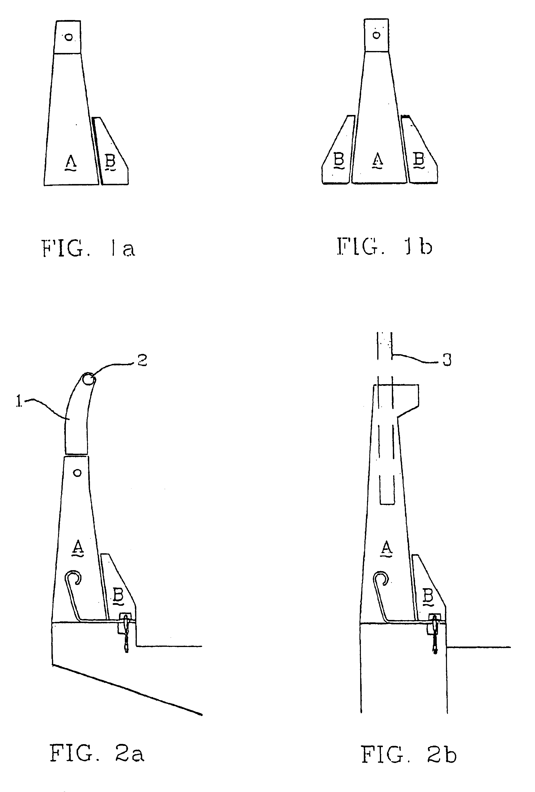
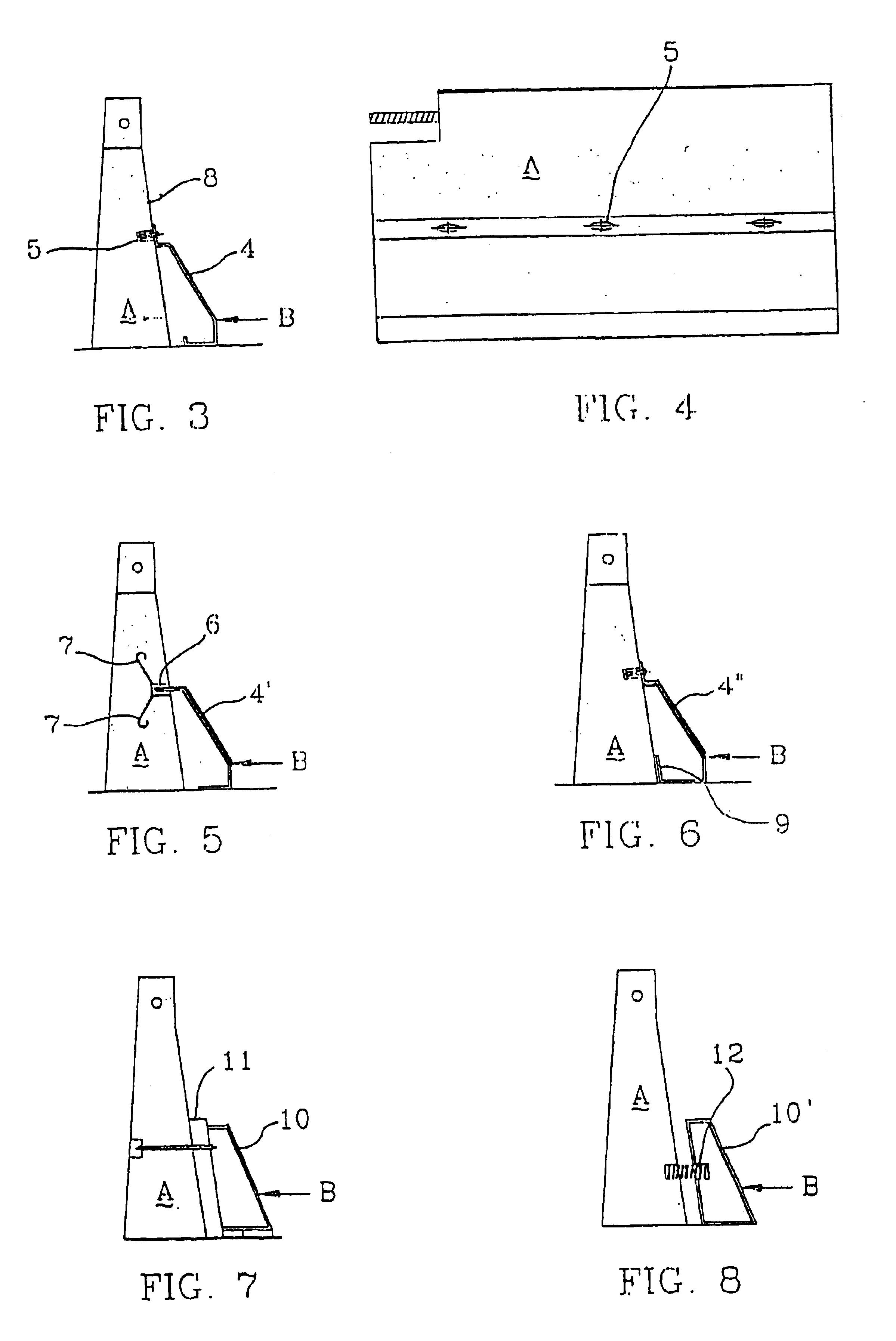
FIGS. 1a and 1b are schematic views of barrier typologies, showing how the barrier of the invention comprises a resistant element A and a dampening element B (in case of an asymmetric barrier for the side of a bridge or of a lateral barrier), or respectively, two dampening elements B (in case of a symmetric single-row type traffic divider). Obviously, the constructive details will be explained in the following description, with reference to the corresponding figures. Moreover, it should be clear that the socle B, while having a shape of a New Jersey socle in FIGS. 1a and 1b, will have—as may be seen also in the following Figs.—a different shape according to particular requirements and to the desired ASI value of the impact deceleration.

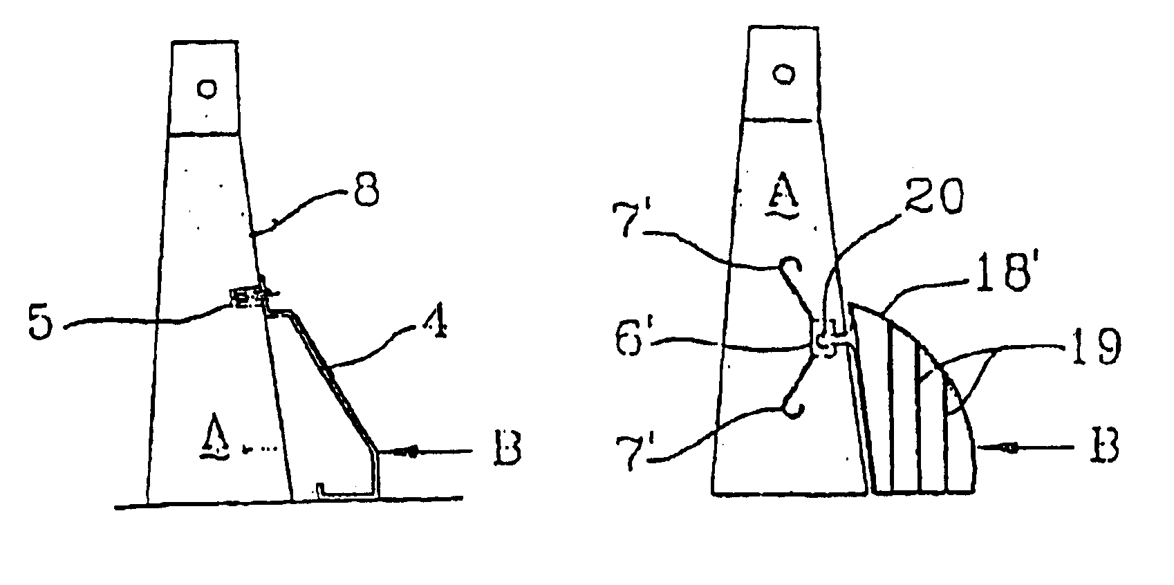
FIGS. 2a and 2b show how the resistant element may be anchored to the curbstone using means known in the art (ductile screw anchors with a predetermined threshold of breakage), and as illustrated in more detail in the description of FIGS. 20, 21, 22. ...


PUM


Abstract

Road safety barrier includes a resistant part and one or two dampening parts for a lateral barrier or a traffic divider respectively. The resistant part of the wall type barrier may be rigidly connected to steel plates which are equally spaced and have been specifically conceived for increasing the resistance during an impact caused by a heavy vehicle. The plates have a slot for the passage of ductile screw anchors, allowing the initial displacement of the resistant part and its connection to the support. If provided, the ductile anchor parts are covered by the dampening part.

Description

TECHNICAL FIELDThe present invention relates to a multipurpose road safety barrier, that is, to a barrier adaptable for being used on the side of a bridge, or as lateral barrier, or as a traffic divider, and which can also be utilized (provided it is appropriately modified) as a support for a sound proofing screen or a screen for protection against the throw of objects. The barrier may be subjected to type approval in various classes corresponding to different resistances, up to the one corresponding to the maximum resistance (H4).The barrier allows to dampen the collision, by way of a controlled deceleration, in case of light motorcars, while stopping the motion of heavy vehicles.BACKGROUND ARTRoad barriers of the wall kind and having a New Jersey (NJ) profile, which are made of monolithic blocks of concrete and which, after their assembling, give rise to a high quality protection, are already known in the art. In those barriers the calibration of the deceleration is obtained, in c...

Claims


Application Information

Patent Timeline
Patent Type & Authority Patents(United States)
IPC IPC(8): E01F15/02E01F15/04
CPCE01F15/043E01F15/0476E01F15/0453
Inventor CAMOMILLA, GABRIELEBRUSCHI, STEFANO
Owner AUTOSTRADE SPA
Why Eureka
Try Eureka