Gas-assisted flare burner

a technology of gas-assisted flare burners and flare burners, which is applied in the direction of incinerator equipment, combustion types, lighting and heating equipment, etc., can solve the problems of manifold life, and achieve the effect of prolonging the life of the manifold and reducing the susceptibility of the flare burner

Inactive Publication Date: 2005-01-11
KELLER MICHAEL R +2
View PDF10 Cites 16 Cited by
  • Summary
  • Abstract
  • Description
  • Claims
  • Application Information

AI Technical Summary

Benefits of technology

The upper end of the shell is reinforced by a generally circular collar, rolled outwards and formed of heavy-gauge metal to provide dimensional stability for the burner gas exit against the heat generated by the burning gas. Preferably, an upper steam distribution sub-assembly is disposed within the collar and includes a ring-shaped steam manifold and secondary steam jets extending beyond the collar to groom the flame, to provide additional air and steam for combusti...

Problems solved by technology

Additionally, locating the steam manifold within the collar shields the manif...

Method used


Image

  • Gas-assisted flare burner
  • Gas-assisted flare burner
  • Gas-assisted flare burner

Examples


Embodiment Construction

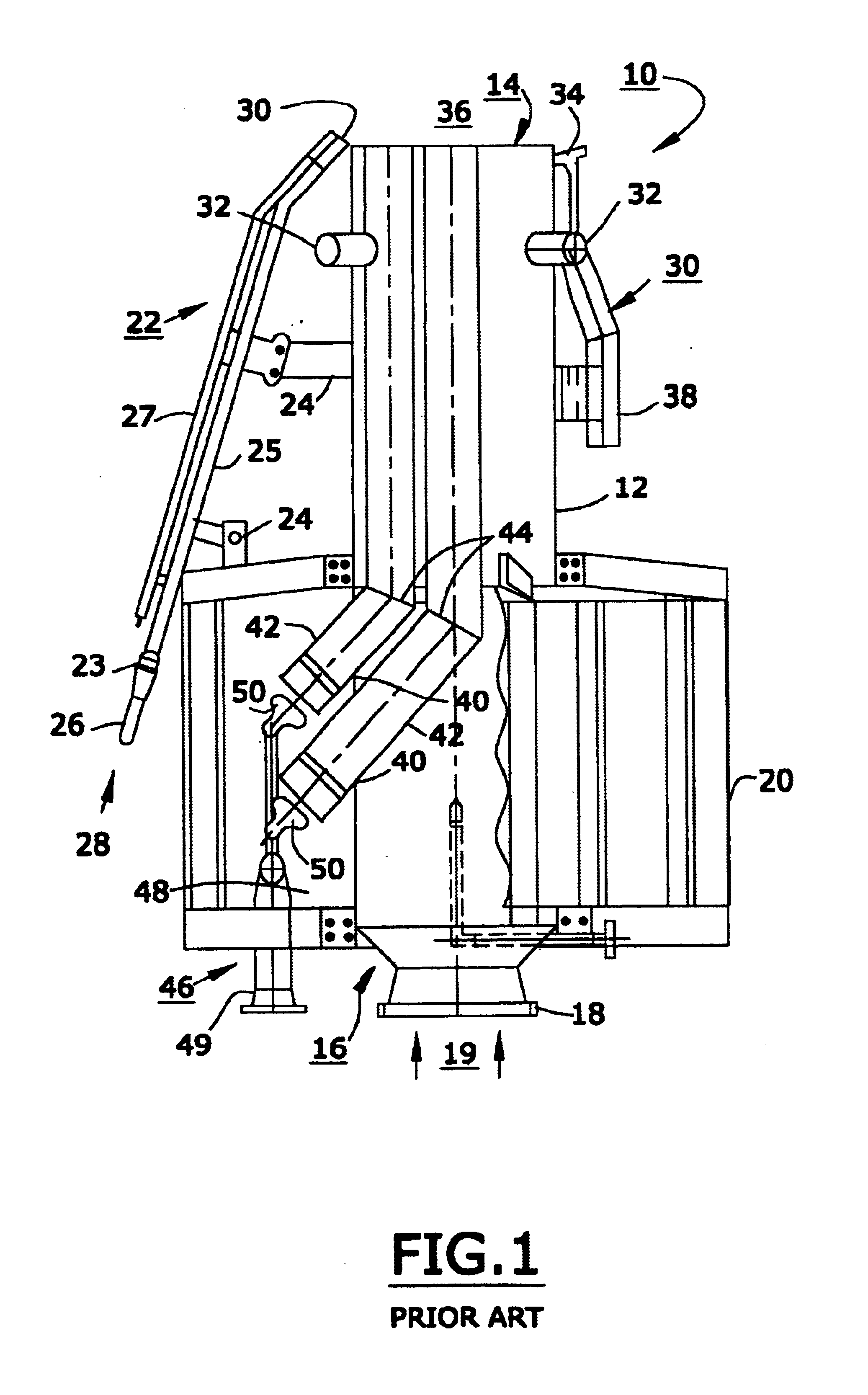
The improvements and benefits afforded by the invention may be better appreciated by first considering a prior art flare burner.

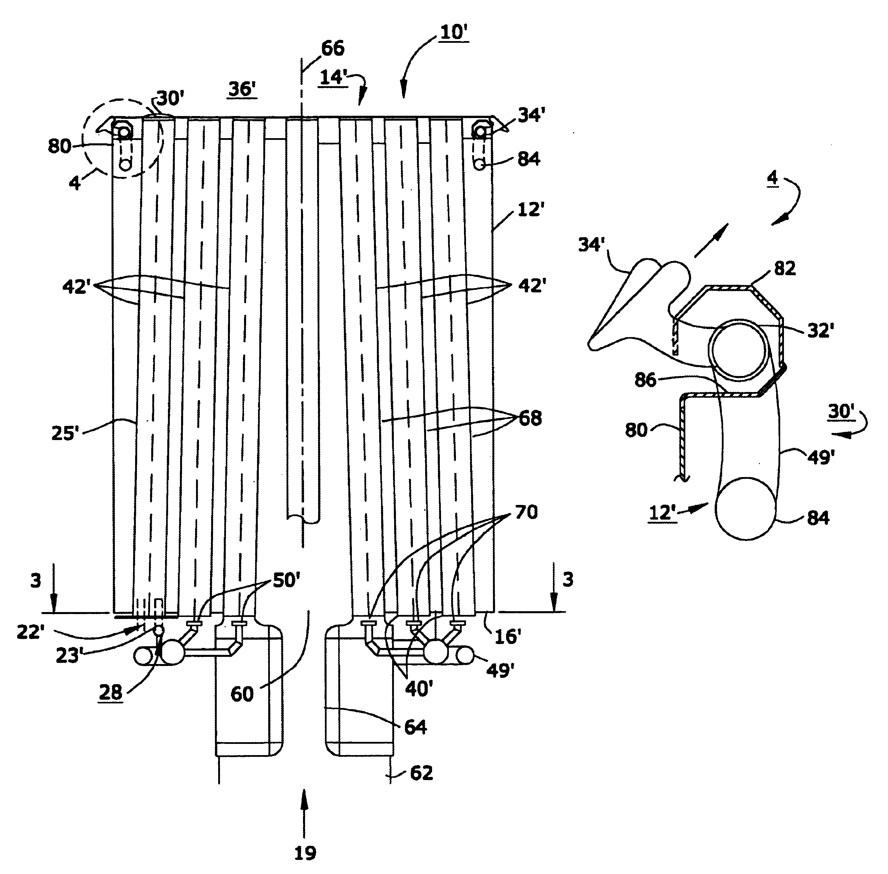
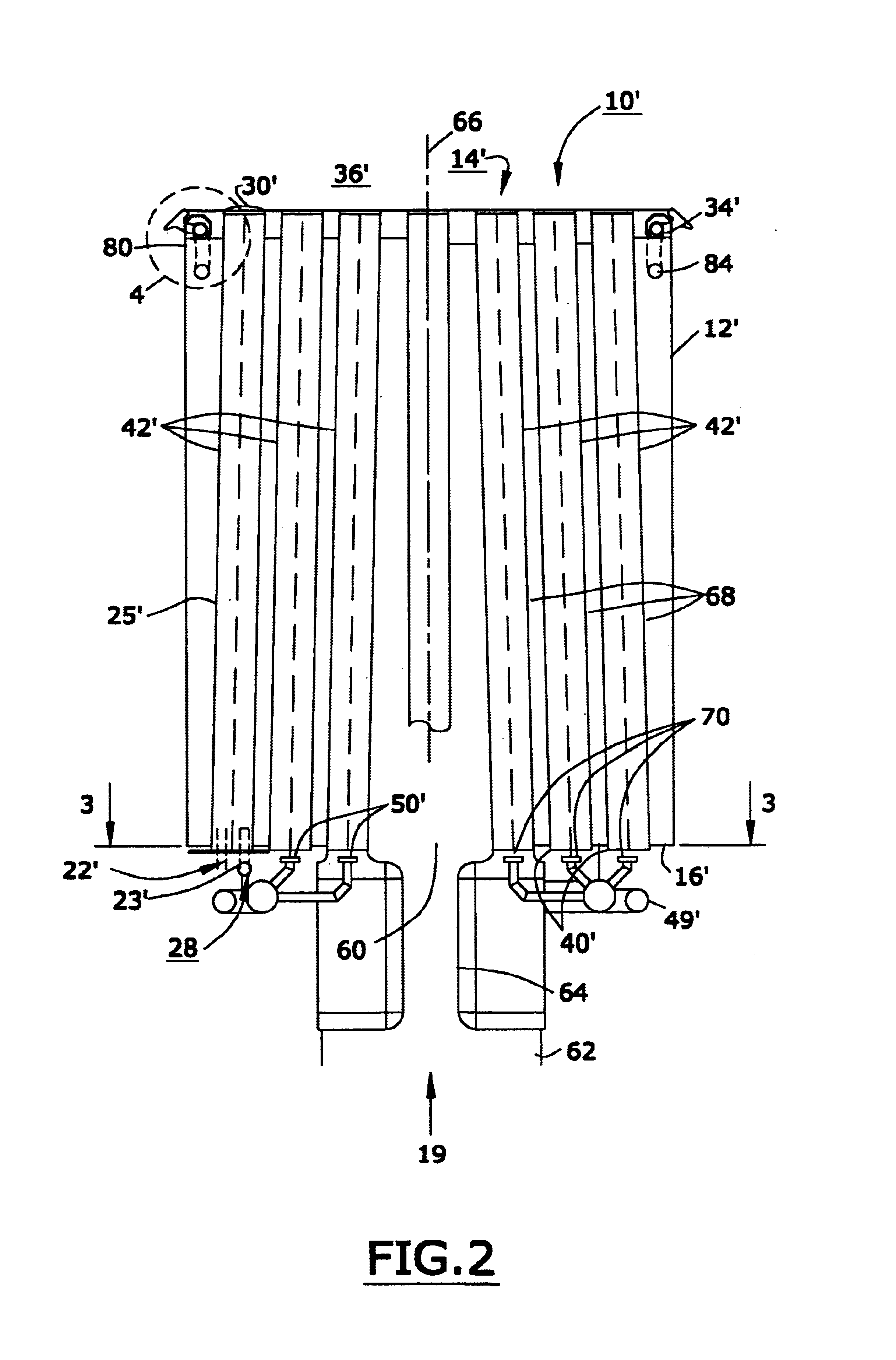
Referring to FIG. 1, a prior art flare burner assembly 10 includes a generally cylindrical shell 12 having an open upper end 14 and a lower end 16 adapted via a fitting 18 for connection to a source (not shown) of gas 19 to be burned, which gas enters shell 12 via fitting 18 during operation of burner 10. Surrounding shell 12 and welded thereto is a cage structure 20 for supporting shell 12 and providing means for mounting burner assembly 10 to a stack structure (not shown). Assembly 10 includes a pilot ignition sub-assembly 22 attached to shell 12 and cage structure 20 via brackets 24 welded to shell 12. Sub-assembly 22 is connectable via a fitting 26 to a source (not shown) of combustible gas 28 which may be the same as gas 19 or not. Pilot ignition sub-assembly 22 includes a gas valve 23, a pilot gas tube 25, and a pilot air tube 27, and has an exit tip ...


PUM


Abstract

An improved flare burner for burning combustible gases in petroleum and petrochemical installations. A cylindrical shell has a closed bottom and an open top. A central opening in the bottom is connectable to a source of the gas to be burned. A plurality of linear steam/gas tubes is disposed within the shell, each tube extending to the open end of the shell and also extending through the shell bottom. A lower steam distribution sub-assembly below the shell bottom includes individual steam jets adjacent the ends of the tubes for educting air to the upper end of the tube. A pilot gas sub-assembly for igniting the flare gas is disposed within the shell. Gas to be burned is passed into the interior of the shell through the bottom opening and moves to the open end. Steam injected into the steam/air tubes educts air, and air and steam exit the tubes and mix with the gas to create a combustible mixture. The pilot light assembly provides an open flame which ignites the mixture. The upper end of the shell is reinforced by a rolled collar. An upper steam distribution subassembly within the collar includes a manifold and jets extending beyond the collar to provide additional air and steam for combustion and prevent fires from overflowing the burner and becoming attached to the outside surface of the shell.

Description

TECHNICAL FIELDThe present invention relates to devices for burning gases; more particularly, to devices for burning gases emanating from petroleum refining or processing operations; and most particularly, to a gas-assisted flare burner having improved resistance to heat deformation and degradation and weather impairment, and increased reliability.BACKGROUND OF THE INVENTIONFlare burners are well known in the art of petroleum processing and refining. See, for example, U.S. Pat. Nos. 4,052,142; 4,070,146; 4,643,669; 4,952,137; and 5,823,759. Typically, a flaring system is provided in a refinery or petrochemical plant to ensure the safe and efficient disposal of relieved gases or liquids, as may occur during normal plant operations or during emergency shutdown of such operations. The disposal fluids are collected in a flare header and routed to the burner. A flare burner is extremely important in the event of a plant emergency such as a fire or power failure, and a properly operating ...

Claims


Application Information

Patent Timeline
IPC IPC(8): F23D14/00F23G7/08F23L7/00
CPCF23L7/005F23G7/085
Inventor KELLER, MICHAEL R.NOBLE, ROGER K.SIMMER, JOHN A.
Owner KELLER MICHAEL R
Why Eureka
Try Eureka