Hydraulic-electronic control systems for marine vessels

a control system and electronic control technology, applied in the direction of marine propulsion, vessel construction, propulsive elements, etc., can solve the problems of inaccuracy of throttle control function and loss of motion, and achieve the effect of eliminating inefficiencies of linkages

Inactive Publication Date: 2005-01-11
MARINE ACQUISITION
View PDF10 Cites 8 Cited by
  • Summary
  • Abstract
  • Description
  • Claims
  • Application Information

AI Technical Summary

Benefits of technology

The invention satisfies the aforementioned needs in the art by providing hydraulic-electronic control systems wherein the throttle position sensor is coupled directly to the hydraulic slave. This eliminates the inefficiencies of the linkages and costly fabrication, and installation of mounting brackets and linkages. An embedded system (e.g., micro-controller) can be used to emulate the signal the engine would receive from the engine manufacturers throttle position sensor. A system according to the invention can also be adapted to include transmission shift and trolling control.

Problems solved by technology

Although this approach is workable, it frequently results in lost motion and, therefore, inaccuracies in the throttle control function.

Method used


Image

  • Hydraulic-electronic control systems for marine vessels
  • Hydraulic-electronic control systems for marine vessels
  • Hydraulic-electronic control systems for marine vessels

Examples


Embodiment Construction

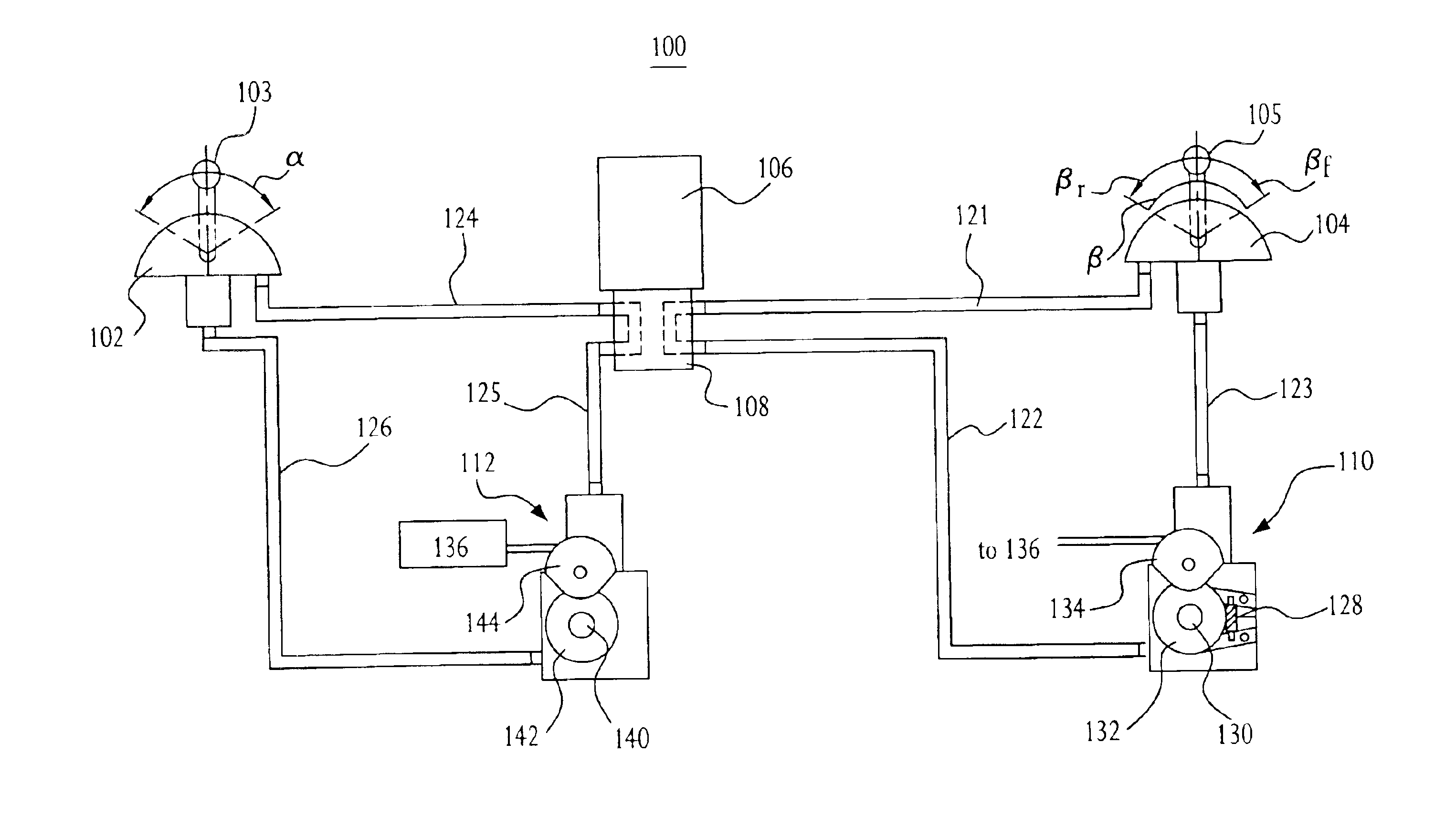
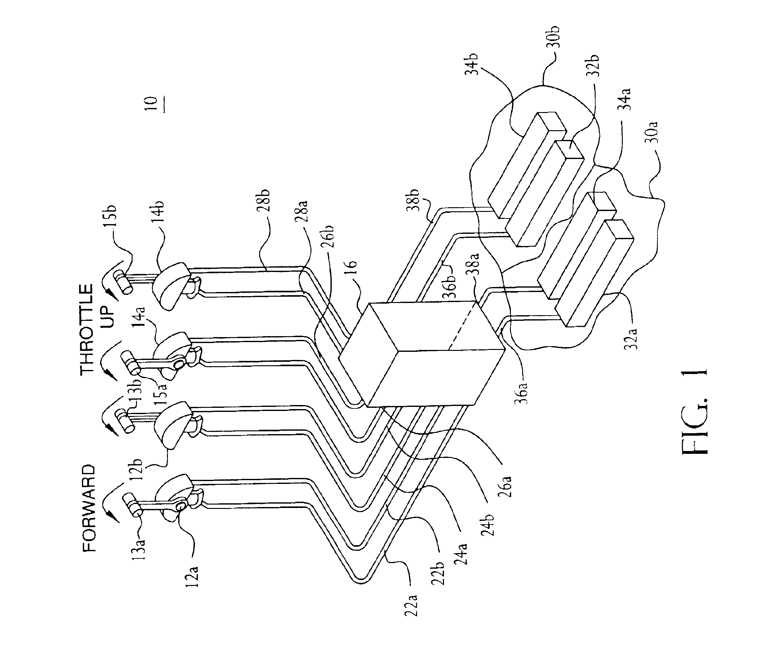
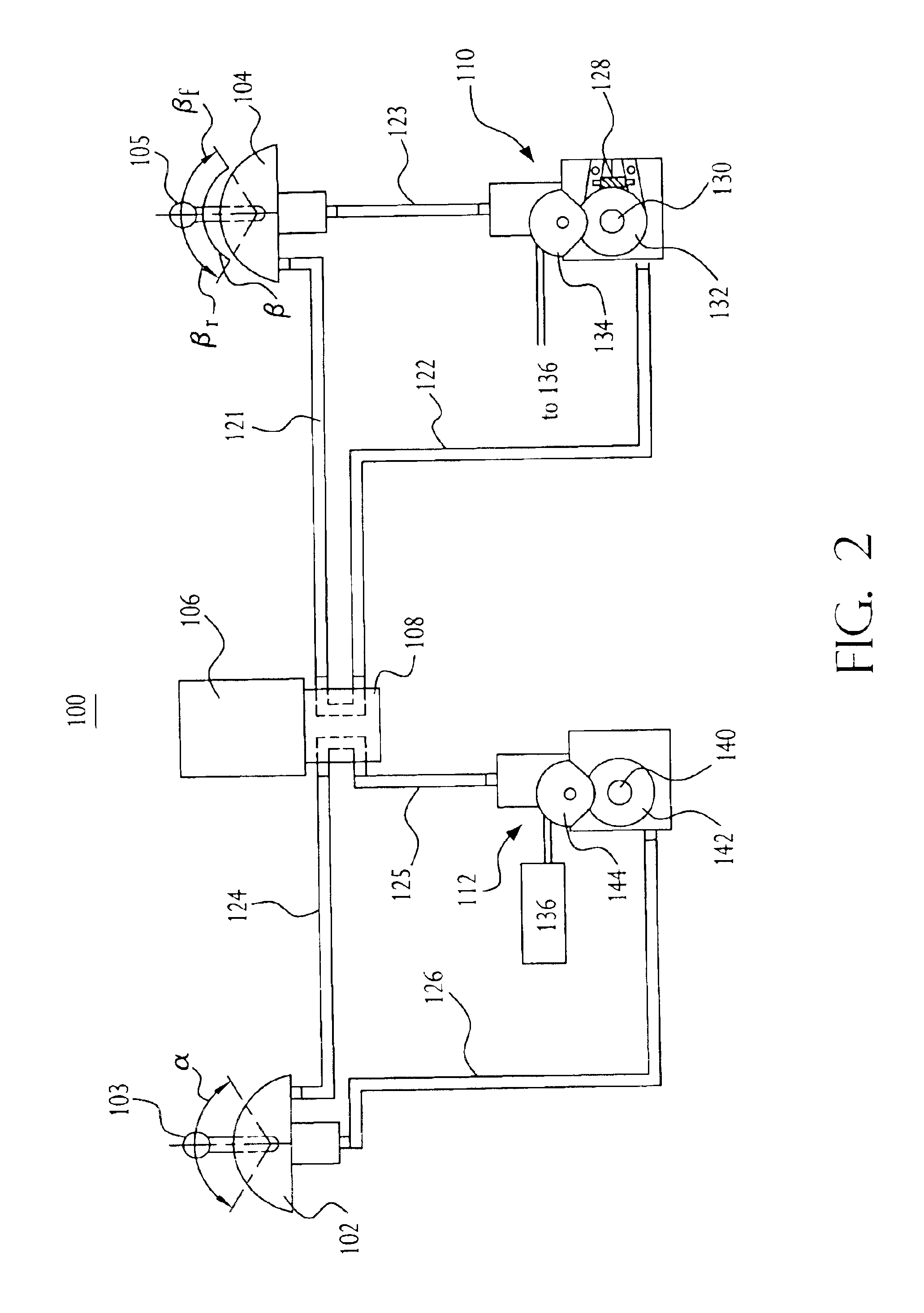
FIG. 1 depicts an electronic control system 10 according to the invention. As shown, the control system 10 can include a first (or port) shift control head 12a, a second (or starboard) shift control head 12b, a first (or port) throttle control head 14a, and a second (or starboard) throttle control head 14b. Though the control system 10 depicted in FIG. 1 includes four control heads, it should be understood that a control system according to the invention can include any number or type of control heads.

Each control head is hydraulically coupled to one or more hydraulic-electronic control unit (HECUs) 16. Preferably, the control heads are coupled to the HECU 16 by one or more hydraulic feed lines. As shown, hydraulic feed line 22a channels hydraulic fluid from the HECU 16 to the port shift control head 12a. Hydraulic feed line 22b channels hydraulic fluid from the port shift control head 12a to the HECU 16. Hydraulic feed line 24a channels hydraulic fluid from the HECU 16 to the port ...


PUM


Abstract

Systems and methods for controlling shift and throttle of an electronically controlled power train are disclosed. The system includes a throttle or shift controller having an operating range. An hydraulic slave is in fluid communication with the controller such that a movement of the controller within its operating range causes a flow or displacement of fluid between the controller and the hydraulic slave. The hydraulic slave has a shaft that rotates in response to the fluid flow between the controller and the hydraulic slave. The shaft is adapted to be coupled to a position sensor such that rotation of the shaft causes the position sensor to produce electrical throttle control signals that represent the movement of the controller within its operating range. The electrical signals can be adapted to cause the power train to set an engine throttle and a transmission shift position according to a current position of the controller within its operating range.

Description

FIELD OF THE INVENTIONThis invention relates to control systems for marine vessels. More particularly, the invention relates to shift and throttle control systems for marine vessels that employ hydraulics to control shift and throttle of an electronically controlled engine.BACKGROUND OF THE INVENTIONMarine vessels frequently employ electronically controlled engines in which throttle and shift are controlled, at least in part, electronically. In such engines, throttle is typically controlled by controlling the output of a potentiometer. Specifically, operation of a throttle control lever, typically located at the bridge, causes rotation of a shaft coupled to a potentiometer so that rotation of the shaft varies the output of the potentiometer. The output of the potentiometer is transmitted to a controller that causes the throttle to vary (i.e., increase or decrease) according to the potentiometer output. Similarly, operation of a shift control lever, which is also typically located at...

Claims


Application Information

Patent Timeline
Patent Type & Authority Patents(United States)
IPC IPC(8): B63H21/00B63H21/22
CPCB63H21/213Y10T477/679Y10T477/6418Y10T477/6433Y10T477/6425
Inventor WINQUIST, TIMOTHYCRAFTCHICK, W. R. TERRENCE
Owner MARINE ACQUISITION
Why Eureka
Try Eureka