Percutaneous bone anchored transferring device

a bone anchored transferring and percutaneous technology, applied in the direction of coupling device connection, infusion needle, sensors, etc., can solve the problems of inability to use commercially available units, inability to pass through the central bore of the implanted unit, and the size of the inner implanted unit to be so small, so as to facilitate the surgical procedure and improve biocompatibility

Inactive Publication Date: 2005-01-11
OSSEOFON
View PDF15 Cites 96 Cited by
  • Summary
  • Abstract
  • Description
  • Claims
  • Application Information

AI Technical Summary

Benefits of technology

The present invention provides a bone-anchored and skin penetrating transferring device and a connecting device designed for daily use. The connecting device comprises a first connection unit, positioned beneath the outer surface of the bone, which transfers electrical information and / or energy, drugs, etc., to an inner implanted unit. The connecting device facilitates the surgical procedure and makes it feasible to replace the inner implanted unit independent of the percutaneous bone anchored transferring device. Furthermore, the new transferring device is designed in such a way that the dimensions are small and achieve better biocompatibility.

Problems solved by technology

In spite of an increasing need for a percutaneous connecting device for permanent use, in particular for the transfer of electrical information and / or electric energy there is no commercially available unit being allowed for clinical use in spite of the fact that there are several patents within the field.
It is believed that the reason that these patents have so far not led to any commercial product is probably due to the fact that the patents describe connecting devices which are either too complicated in that they contain too many poles and ingoing components or that they do not attend to all the intricate demands raised from biocompatibility, anatomical, surgical, electrical, patient safety and handling points of view.
When it comes to practical realization of the electric connecting device described in U.S. Pat. No. 5,562,670 there is a weakness in that the implanted set of cables and the inner implanted unit have to be so small that they can pass through the central bore of the implant.
For most applications, however, the inner implant is too large to be able to pass through the central bore of the implant.
Fixation of the implant using threads has the disadvantage that the bone anchored part of the implant has to have a diameter large enough to encompass the thread, which clearly restricts the possibilities to encompass connecting components therein as well.
Furthermore, a screw implant has to be rotated during the application which means that an asymmetrical design of the implant is very hard to realize.
Furthermore, practical problems will result because the inner implanted unit has to rotate together during application if it has been pre-mounted and passes through the transferring device due to the fact that it is too large to be applied afterwards through the bore.
Such design would lead to a potential risk for bacterial accumulation and risk for skin irritation.
Additionally, the design according to this patent, is subject to the same weaknesses as described above with reference to patent U.S. Pat. No. 5,562,670.
Problems reported in clinical tests using such an arrangement shows that the set of cables having a realistic minimum diameter of 1 to 2 mm and being a little elastic creates a biocompatibility problem at the skin penetration area, probably due to the occurrence of small movements between the mobile skin and bone with a foreign material there between.
Furthermore, the necessary skin reduction can be jeopardized if the set of cables does not have a very small diameter.
This connecting technique further means that rotation of the outer connecting part is not possible and that the device is not protected from excessive external forces.
The flange of the actual connecting device hinders the skin from growing to the bone / bone connecting tissue, and the frequency of skin complications can be expected to be relatively high.
Furthermore, the whole connecting device is placed outside both the bone and the skin, which means that it will extend a considerable distance above the skin surface.
Even small movements of the implant relative to the skin will lead to a great risk for skin irritation.
Due to the fact that even small movements between skin and implant create irritation, this type of connecting devices should only be used temporarily.
As the implant is manufactured in an elastic material, which is provided with slots, the implant can not be used for a bone anchored percutaneous transferring device.

Method used


Image

  • Percutaneous bone anchored transferring device
  • Percutaneous bone anchored transferring device
  • Percutaneous bone anchored transferring device

Examples


Embodiment Construction

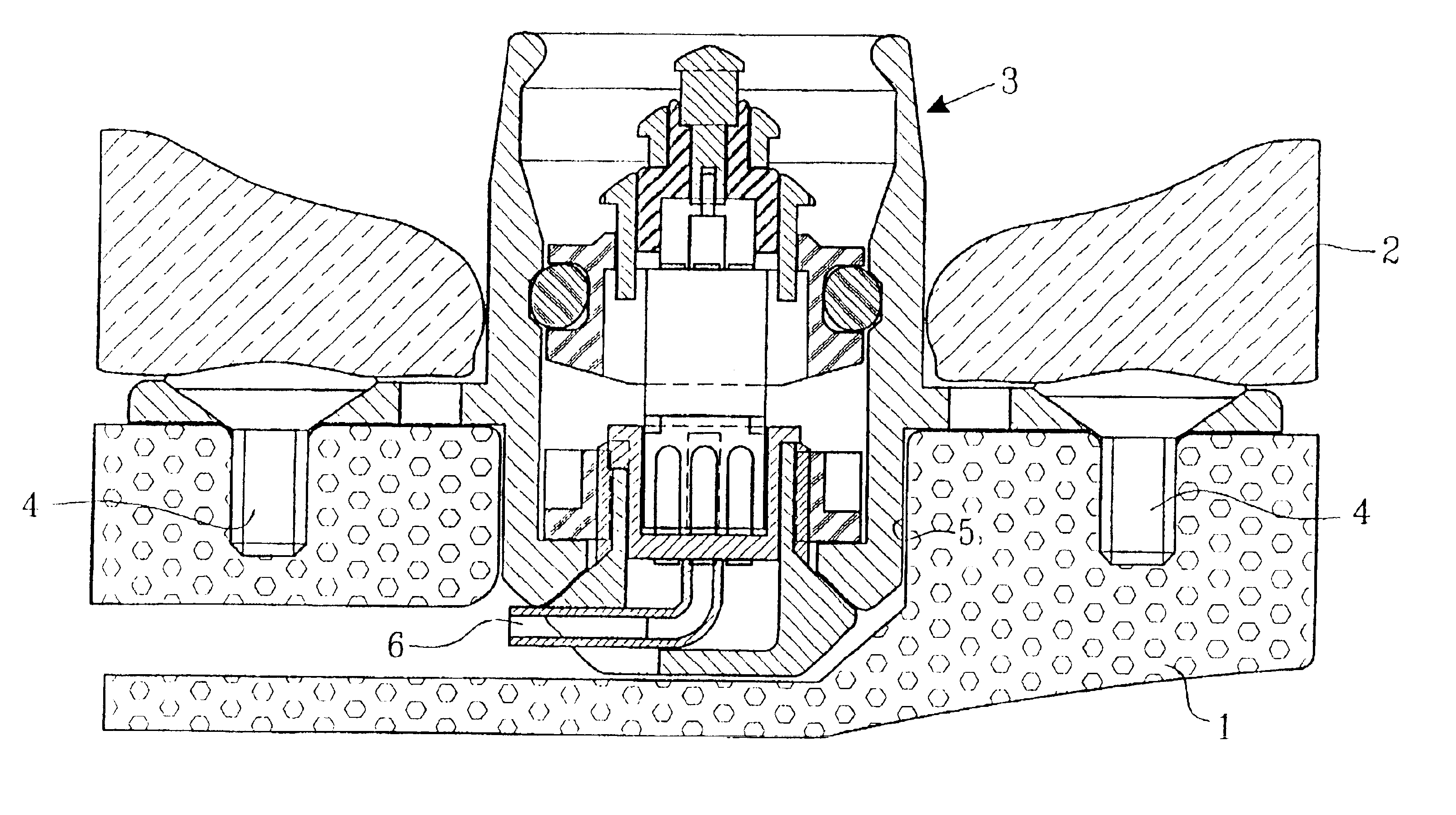
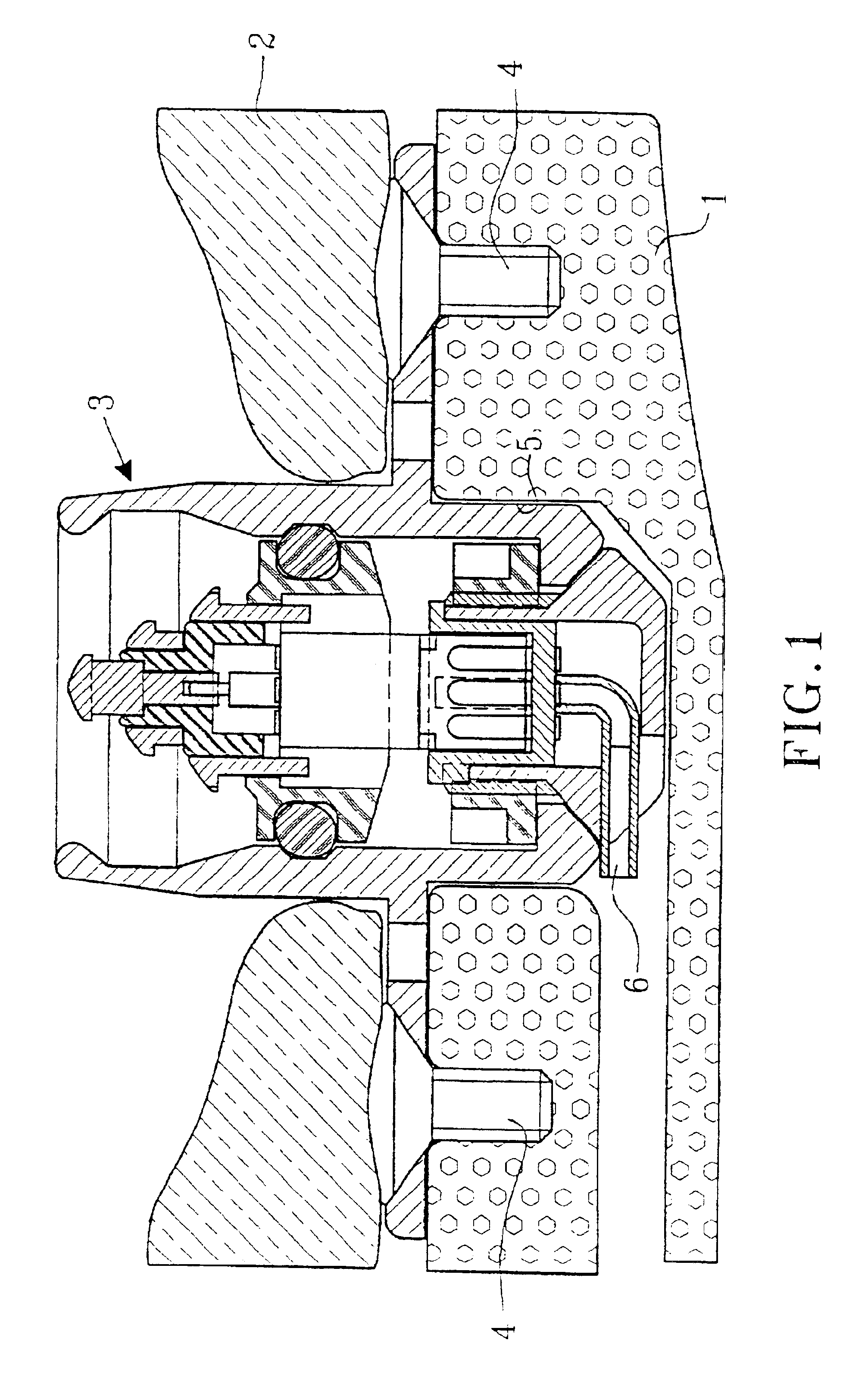
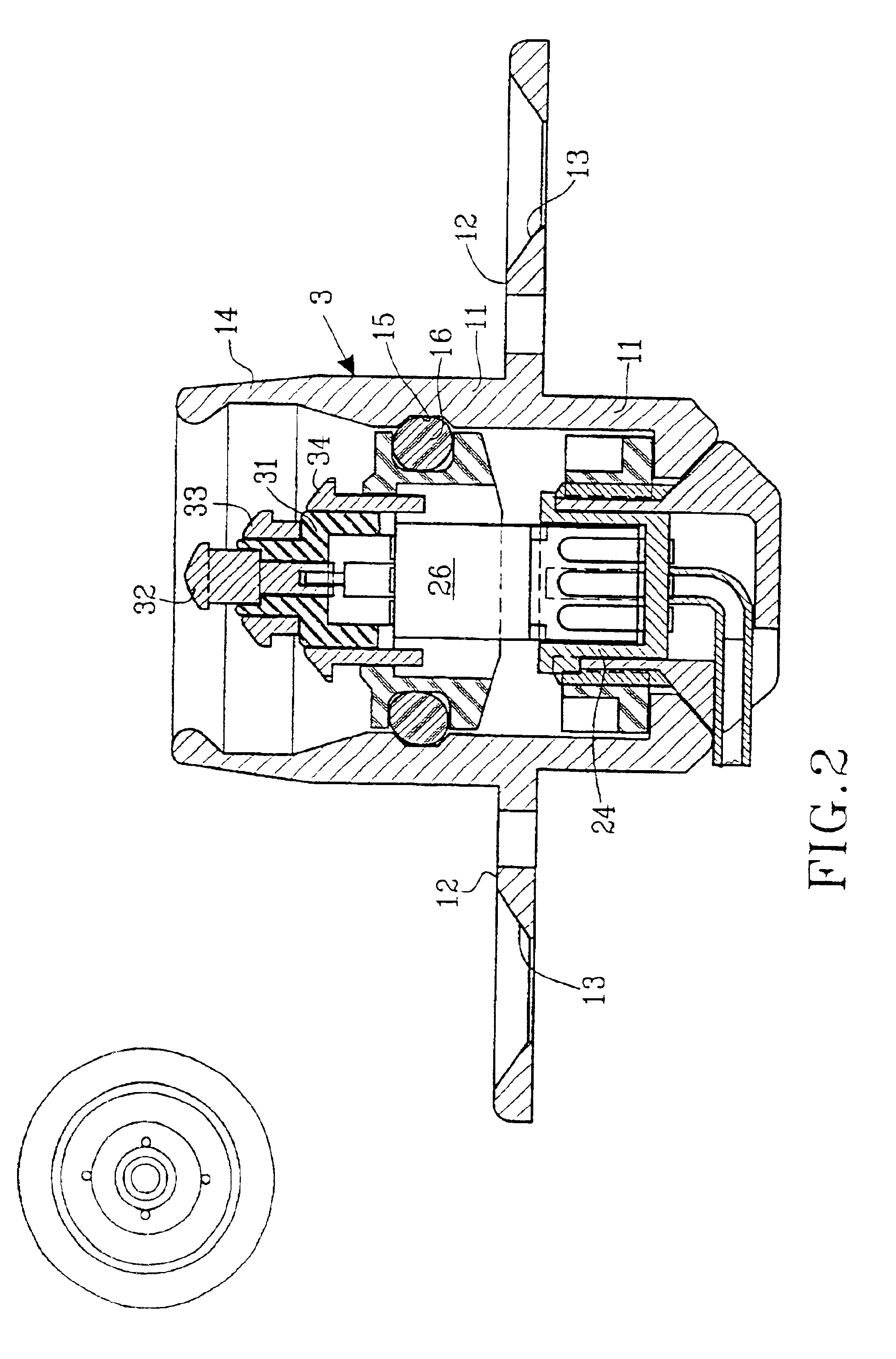
As mentioned above there is a great demand within several medical-technical applications for a means to transfer electrical information and / or electric energy or to communicate in another way (e.g. to distribute drugs or to air out interior cavities and cell systems) from an outer unit to a subcutaneously implanted inner unit. Such subcutaneously implanted units can be hearing assistive aids, e.g. cochlear implants, middle ear implants, bone conduction devices, devices for suppression of tinnitus, and other medical-technical aids, e.g. tubes, cannulas, stimulators of different types, registration means for biological signals, pumps for distribution of drugs, evacuation of liquids, etc. In principle, such devices consist of the following essential parts: outer unit, connecting device, skin penetrating and bone anchored transferring device, set of cables / communication channel, and subcutaneously implanted inner unit. A principal arrangement utilizing a transferring device according to...


PUM


Abstract

The present invention relates to a percutaneous bone anchored transferring device and a connecting device for obtaining a transfer of an electrical signal and / or energy and / or distribution of a drug and / or airing of a body cavity and a system and a method for using the same.

Description

BACKGROUND OF THE INVENTIONThe present invention relates to a percutaneous (skin penetrating) bone anchored transferring device and a connecting means, preferably by means of which an outer device can be connected to an inner implanted subcutaneous unit.In spite of an increasing need for a percutaneous connecting device for permanent use, in particular for the transfer of electrical information and / or electric energy there is no commercially available unit being allowed for clinical use in spite of the fact that there are several patents within the field. It is believed that the reason that these patents have so far not led to any commercial product is probably due to the fact that the patents describe connecting devices which are either too complicated in that they contain too many poles and ingoing components or that they do not attend to all the intricate demands raised from biocompatibility, anatomical, surgical, electrical, patient safety and handling points of view. Some of th...

Claims


Application Information

Patent Timeline
Patent Type & Authority Patents(United States)
IPC IPC(8): A61F11/04A61F11/00A61M1/00H04R25/00
CPCA61M39/0247H04R25/606A61M2039/025A61M2039/0267H04R2225/67A61M2039/0279A61M2039/027
Inventor H.ANG.KANSSON, BO
Owner OSSEOFON
Why Eureka
Try Eureka