Dielectric recording medium, and method of and apparatus for producing the same

a recording medium and dielectric technology, applied in the field of dielectric recording medium, can solve the problems of difficult to make the medium thinner, long measurement time, and limited method of mechanical polishing, and achieve the effect of quick polishing

Inactive Publication Date: 2005-01-11
PIONEER CORP +1
View PDF2 Cites 64 Cited by
  • Summary
  • Abstract
  • Description
  • Claims
  • Application Information

AI Technical Summary

Benefits of technology

According to this aspect, the edge portion of the electric conductor is located at the peripheral portion of the recording surface. The edge portion of the electric conductor is connected with the main body of the electric conductor covering the back surface of the dielectric material through the electric conductor covering a side surface of the dielectric material. Therefore, the same electric potential as that of the main body of the electric conductor is set in the edge portion of the electric conductor. If the probe moves out of the recording surface, the probe contacts with the edge portion of the electric conductor. Therefore, the fact that the probe moves out of the recording surface can be electrically detected. Thus, the moving of the probe can be controlled on the basis of a result of the detection. If the edge portion of the electric conductor is arranged so as to surround the recording surface, the fact that the probe moves out of the recording surface can be detected in all directions. Moreover, according to this aspect, since the edge portion of the electric conductor is located at the peripheral portion of the recording surface, it is possible to remove electric charge on the recording surface rapidly. If the edge portion of the electric conductor is arranged so as to surround the peripheral portion of the recording surface, the ability to remove the electric charge can be improved.
According to this aspect, in the etching of the dielectric material until reaching the conductive thin film, firstly, the dielectric material can be quickly polished by the mechanical polishing device with the predetermined thickness left, which does not reach the conductive thin film. Secondly, the dielectric material can be accurately etched by the dry etching, until the conductive thin film surrounding the recording area appears.

Problems solved by technology

However, the method by the mechanical polishing is limited in thinning the medium with a thickness on the order of several μm, even using an angle polishing method of polishing a crystal with its back surface inclined slightly to the surface of a polishing apparatus.
It is also difficult to make it thinner while keeping a stable form because the lack of crystal strength causes fracture.
However, it takes a long time to measure it.
Especially, in the case of treating a large crystal whose one side is on the order of mm, it is extremely difficult to polish all of the crystal surfaces in a uniform thickness to prepare the thin film.

Method used


Image

  • Dielectric recording medium, and method of and apparatus for producing the same
  • Dielectric recording medium, and method of and apparatus for producing the same
  • Dielectric recording medium, and method of and apparatus for producing the same

Examples


Embodiment Construction

Embodiment Associated with the Dielectric Recording Medium

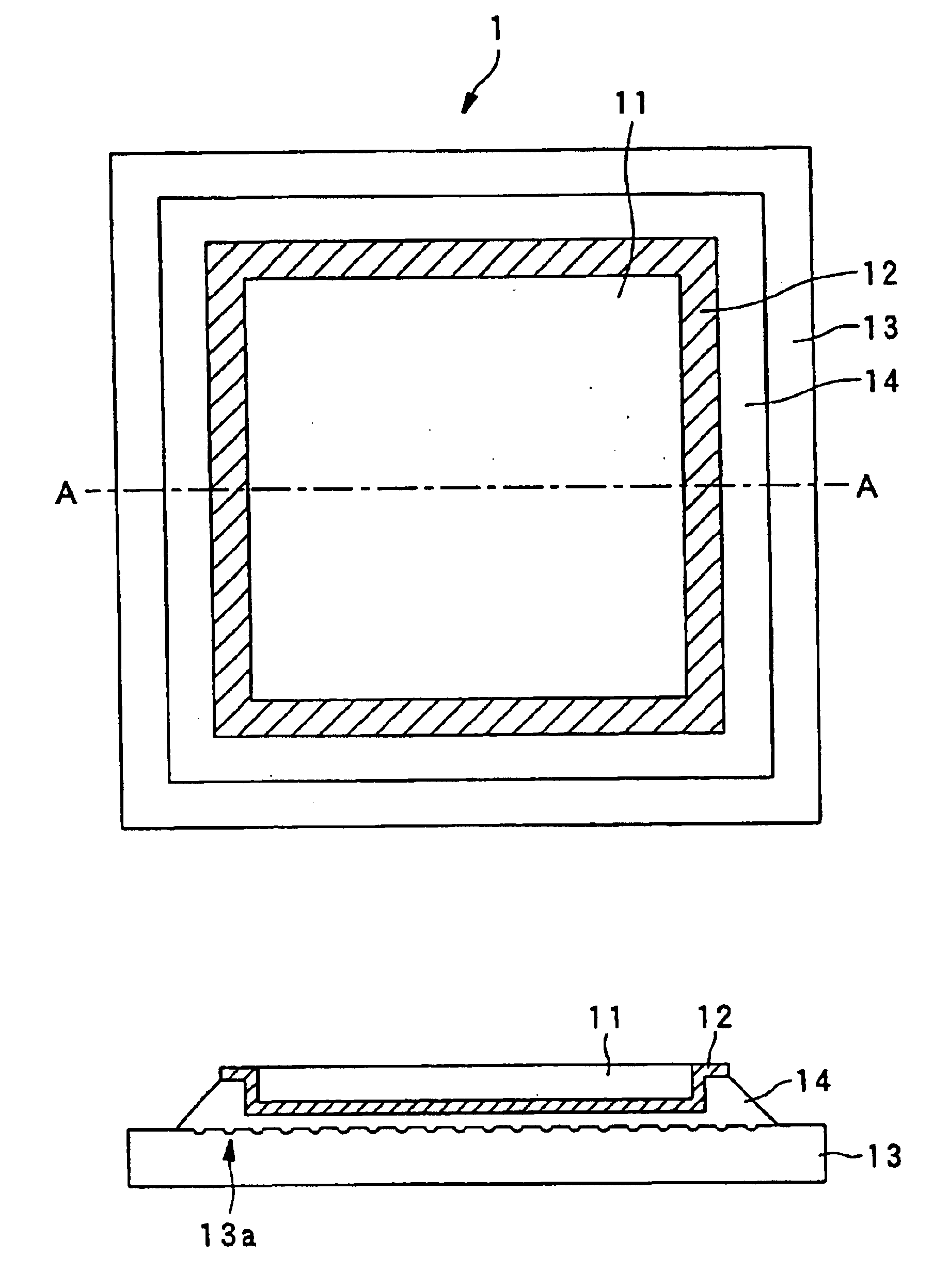
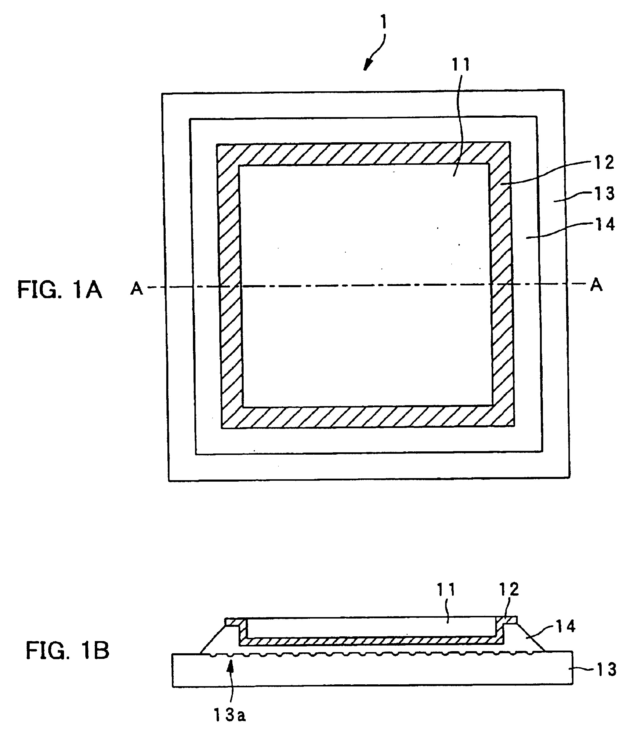
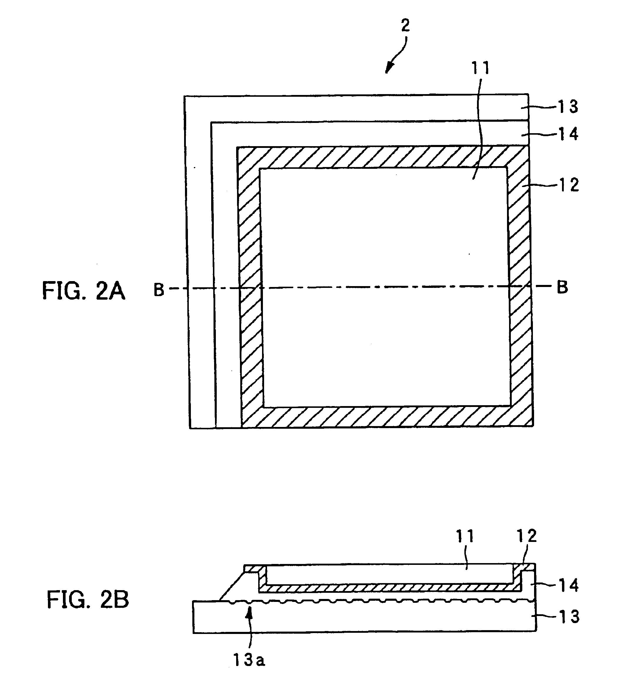
The embodiment of the dielectric recording medium of the present invention will be explained with reference to FIG. 1A to FIG. 4B. FIG. 1A is a plan view showing a first embodiment of the dielectric recording medium of the present invention. FIG. 1B is an A-A cross sectional side view of FIG. 1A. FIG. 2A is a plan view showing a second embodiment of the dielectric recording medium of the present invention. FIG. 2B is a B-B cross sectional side view of FIG. 2A. FIG. 3A is a plan view showing the preparation of the dielectric recording medium shown in FIG. 2A and FIG. 2B. FIG. 3B is a C-C cross sectional side view of FIG. 3A. FIG. 4A and FIG. 4B are plan views showing the preparation forms of the dielectric recording medium of the present invention, FIG. 4A showing a mask layout in the case of a single dielectric recording medium, and FIG. 4B showing a mask layout in the case of a plurality of dielectric recording media.

A diele...


PUM

PropertyMeasurementUnit
lengthaaaaaaaaaa
thickaaaaaaaaaa
polarization domain sizeaaaaaaaaaa

Abstract

The dielectric recording medium is provided with a dielectric material, a conductive thin film, and a substrate. The conductive thin film and the substrate are bonded by a resin adhesive. The dielectric material is constructed of a ferroelectric single crystal having a uniform thickness, and its one surface is used for a recording and / or reproducing surface, on the order of mm on a side and about 5000 Å thick. The conductive thin film, about 1000 to 2000 Å thick, is placed on a surrounding portion and a back surface of the recording and / or reproducing surface of the dielectric material. The substrate is intended to preserve the thin dielectric material and maintain the planarity, and concave portions are formed on the adhesive surface. The concave portions absorb excessive resin adhesive when the dielectric material is bonded onto the substrate, which makes the adhesive surface uniform and flat.

Description

BACKGROUND OF THE INVENTION1. Field of the InventionThe present invention relates to a dielectric recording medium for recording information in a dielectric material, and a method of and an apparatus for producing the dielectric recording medium.2. Description of the Related ArtRecently, many types of dielectric materials have been developed, and most of them are used for ultrasonic elements, optical elements, a memory and the like. In accordance with the fact, a method of measuring a spontaneous polarization distribution of the dielectric material and local anisotropy of the piezoelectric material has been developed. Also, by using this technique, techniques of recording information in the dielectric material and reproducing the information have been developed.In order to record information in the dielectric material, a polarization direction of the polarization domain of the dielectric substance is formed such that the polarization direction corresponds to the information. For exa...

Claims


Application Information

Patent Timeline
Patent Type & Authority Patents(United States)
IPC IPC(8): C04B37/02G11B9/00G01Q80/00G11B9/02
CPCB82Y10/00C04B37/028G11B9/14G11B9/1463G11B9/1472G11B9/02C04B2237/30C04B2237/345Y10T428/24777Y10T428/219
Inventor ONOE, ATSUSHICHO, YASUO
Owner PIONEER CORP
Why Eureka
Try Eureka