Flat cable and modular rotary anvil to make same

a technology of flat cable and rotary anvil, which is applied in the direction of flat/ribbon cable, insulated conductor, cable, etc., can solve the problems of inability to use flat cable, inability to make flat cable, and need to be discarded, so as to achieve low cost

Inactive Publication Date: 2005-01-11
METHODE ELETRONICS INC
View PDF35 Cites 19 Cited by
  • Summary
  • Abstract
  • Description
  • Claims
  • Application Information

AI Technical Summary

Benefits of technology

It is another object of the invention to provide a flat electrical cable that is light in weight.
It is a further object of the invention to reduce the number of tools required to be kept in inventory for producing the flat electrical cable.
It is another object of the invention to increase the variety of tool sets being run at the same time.
It is another object of the invention to provide a method of assembling a flat cable by bonding without using adhesives and to provide the capability of forming a continuous seam and other types of seams.
It is yet another object of the invention to provide for a low cost flat electrical cable.

Problems solved by technology

However, use of adhesive to bond the layers is disadvantageous in that upon heating of the adhesive, the conductors may float in the free flowing adhesive causing the spacing between the conductors to be inconsistent and non-parallel.
Upon drying and attempted attachment of the flat cable to a component, the improperly placed conductor may not align with the conductive leads of the component the cable is to be attached and, thus, the flat cable is unusable and must be discarded.
Further, when the cable is stripped to expose the conductors for connection of the cable to a component, the conductors have an adhesive residue thereon which inhibits the conductive properties of the conductor.
Also, if any scrap material of the insulator layers is produced, the scrap may not be recycled due to the presence of the adhesive on the insulator layer.
Therefore, the known methods of welding thermoplastic materials using ultrasonics did not provide for a continuous welded seam where the seam has great pull strength.
In the area of electrical cables, seams of great pull strength are required and the previously known welding techniques are not sufficient.

Method used


Image

  • Flat cable and modular rotary anvil to make same
  • Flat cable and modular rotary anvil to make same
  • Flat cable and modular rotary anvil to make same

Examples


Embodiment Construction

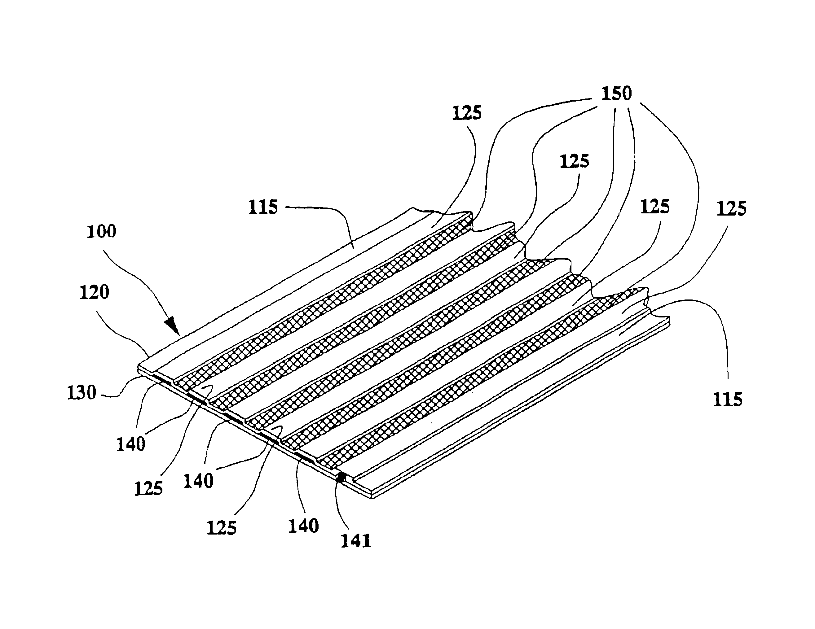
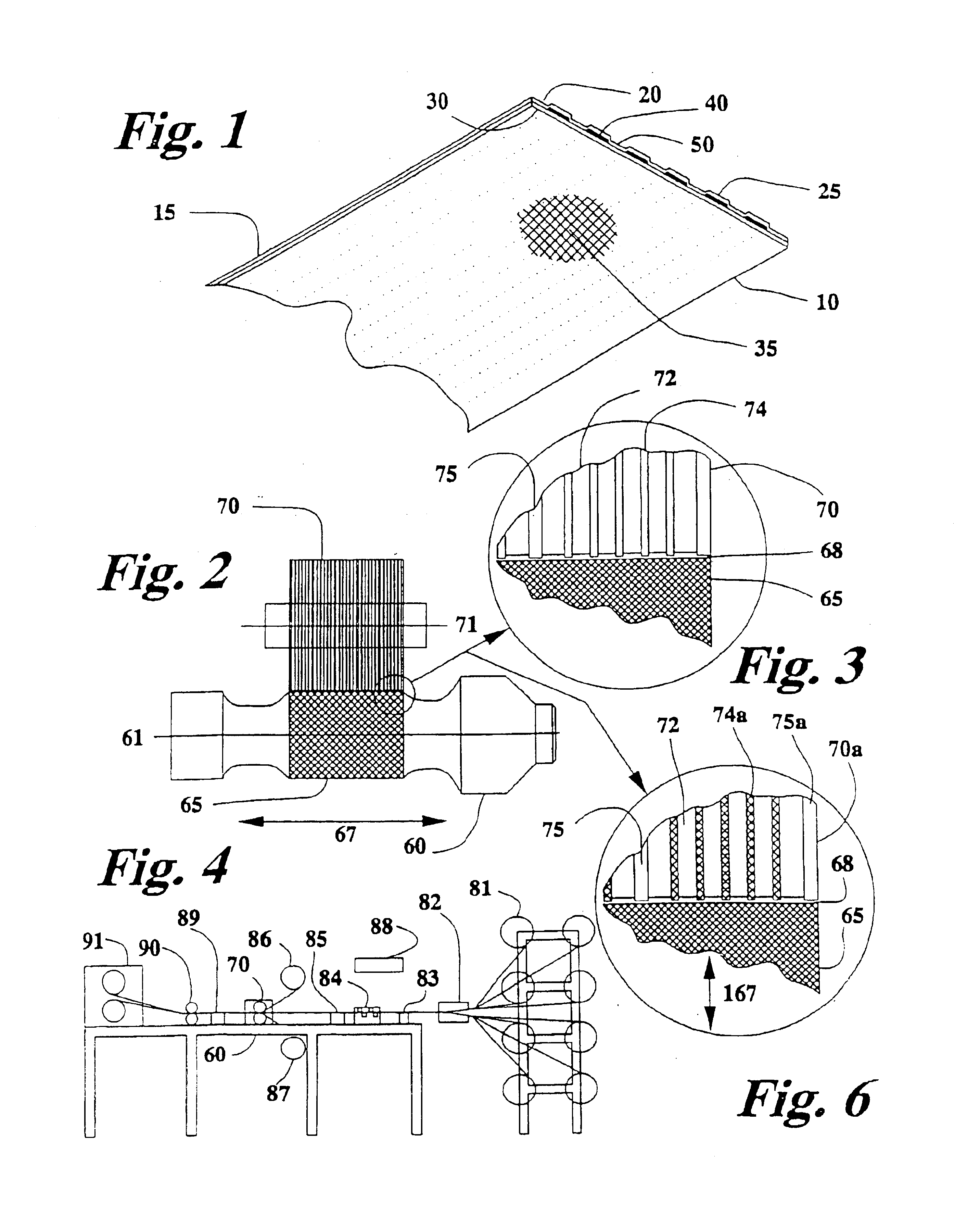
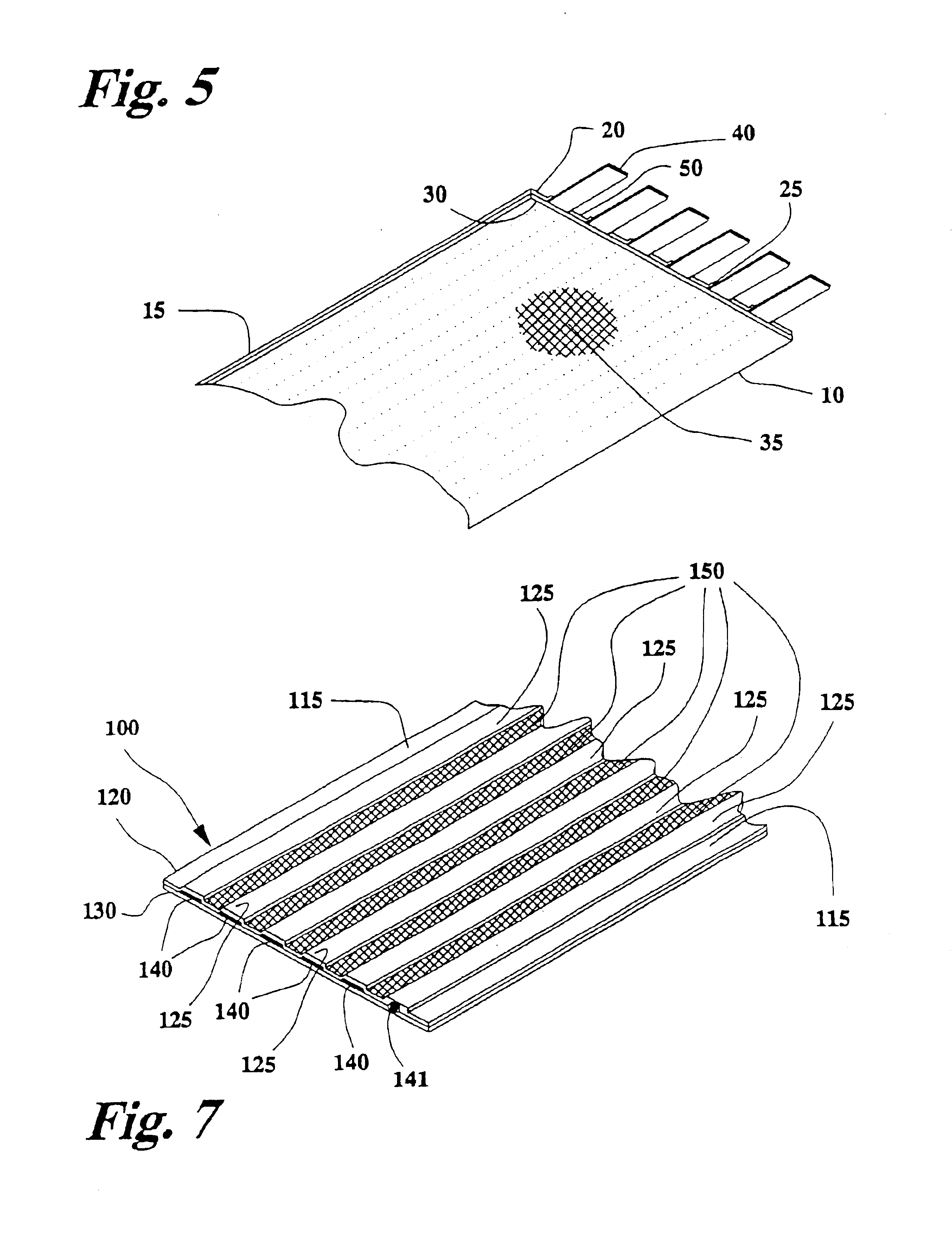
Referring now to the drawings, wherein like reference numerals designate identical or corresponding parts throughout the several views, and more particularly to FIG. 1 thereof which shows a finished flat conductor cable 10 of a preferred embodiment of the present invention. The flat cable 10 has an upper layer 20 and a lower layer 30 formed of an insulating material. In a preferred embodiment, polyester insulator is used, such as that having a thickness of 0.001 inches. However, thicker insulator materials may be used to provide stronger bonds, such as where the seams are narrow. Intermediate the upper and lower layers 20, 30 are conductors 40. The conductors 40 are made of individual strands of metallic material which lie substantially parallel to one and another along the length of the cable 10. In a preferred embodiment, the conductors are formed of annealed copper having a dead soft hardness rating. However, any other conductor may be used such as copper clad steel. Furthermore,...


PUM

PropertyMeasurementUnit
linear densityaaaaaaaaaa
thicknessaaaaaaaaaa
lengthaaaaaaaaaa

Abstract

A flat electrical cable and a modular rotary anvil for assembling a flat electrical cable is provided wherein the flat cable includes an upper and lower layer. The upper layer has ribs protruding along its length that are substantially parallel to one another, and continuous substantially parallel and adjacent seams formed therebetween. Conductors are placed between the upper and lower layers adjacent the seams. The present invention may have upper and lower polyester layers having copper conductors therebetween and the seams ultrasonically welded in order to provide a flat electrical cable for various applications such as incorporation in an automobile clockspring. The modular rotary anvil includes multiple removable and interchangeable segments or inserts which provide the ability to impart a smooth or knurled interchangeable segments or inserts which provide the ability to impart a smooth or knurled textured surface pattern to the work-piece. Other inserts include cutting inserts which provide for a seam on the work-piece while a the same time cuts the work-piece along a seam—segments or inserts which provide the ability to impart a smooth or knurled textured surface pattern to the work-piece. Other inserts include cutting inserts which provide for a seam on the work-piece while a the same time cuts the work-piece along a seam.

Description

BACKGROUND OF THE INVENTION1. Field of the InventionThe present invention pertains to flat cable and an apparatus for making flat cable. The invention more particularly concerns flat electrical cable with exposed conductors without adhesive residue and a modular rotary anvil which is used to manufacture the flat electrical cable.2. Discussion of the BackgroundFlat electrical cables are well known in the art having conductors sandwiched between two insulating layers. Flat conductor cable is known in the art having an upper insulator layer having an adhesive adhered to a first side of the upper layer and a lower layer of insulating material having an adhesive adhered to a first side of the lower layer. A conductor or strands of conductors are placed between the upper and lower insulator layers and all three layers are secured together by the adhesive. However, use of adhesive to bond the layers is disadvantageous in that upon heating of the adhesive, the conductors may float in the fr...

Claims


Application Information

Patent Timeline
Patent Type & Authority Patents(United States)
IPC IPC(8): B29C65/08H01B7/08H05K3/28H05K1/00H01R39/00B29C65/00B29C65/02H01B7/00H01B13/00
CPCB23K20/106B29C65/087B29C66/1122B29C66/433B29C66/81461B29C66/8165B29C66/8167B29C66/8322B29C66/83411B29C66/83413B29C66/84121H01B7/0009H01B7/0018H01B7/0838H05K3/281B29C65/081B29C65/085B29C66/845B29C66/81433B29C66/81435B29C66/93451B29C66/9513B29C66/939B29K2067/00B29L2031/3462H05K1/0393H05K2203/0285H05K2203/065B29C66/9516Y10T29/49117Y10T29/49162Y10T29/53243Y10T29/53213Y10T428/24496Y10T29/53217Y10T29/53187Y10T428/24529Y10T29/49201Y10T29/5313Y10T29/532Y10T29/49194B29C66/934B29C65/00B29C65/086B29C65/7455B29C66/232B29C66/71B29C66/73162B29C66/73921B29C66/73941B29C66/81811B29C66/8432
Inventor SCHILSON, TOMKAMPS, STEVE
Owner METHODE ELETRONICS INC
Why Eureka
Try Eureka