Microelectromechanical tunneling gyroscope and an assembly for making a microelectromechanical tunneling gyroscope therefrom
Inactive Publication Date: 2005-01-11
HRL LAB
View PDF30 Cites 12 Cited by
Summary
Abstract
Description
Claims
Application Information
AI Technical Summary
This helps you quickly interpret patents by identifying the three key elements:
Problems solved by technology
Method used
Benefits of technology
[0005]MEM gyroscopes may be used in various military, navigation, automotive, and space applications. Space applications include satellite stabilization in which MEM technology can significantly reduce the cost, power, and wei
Problems solved by technology
None of these bulk micromachining processes allow one to fabricate a single crystal Si cantilever (with no deposited layers over broad areas on the beam which can produce the
Method used
Image
Click on the blue label to locate the original text in one second.
Reading with bidirectional positioning of images and text.
Examples
Embodiment Construction
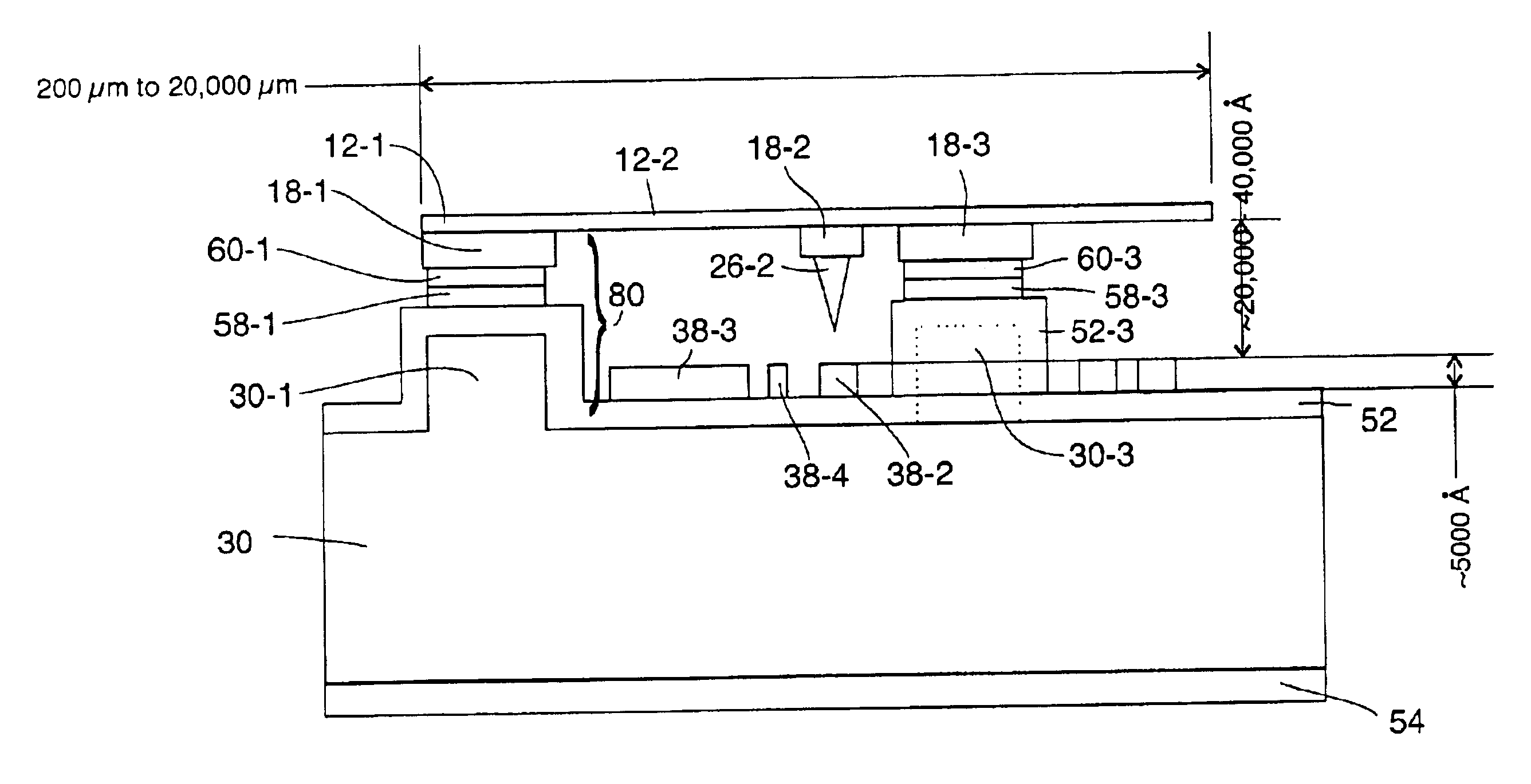
structures are joined one to another at the bonding layer. The bonding layer also bonds the first and second portions of the side drive electrodes together.
[0008]In operation, a Coriolis force is produced normal to the plane of the device by oscillating the beam laterally across the substrate. The side drive electrodes are preferably fabricated with the cantilevered beam on the first substrate and are bonded to the second substrate at the same time that the cantilevered beam is attached. This provides for high alignment accuracy between the cantilevered beam and the side electrodes.
BRIEF DESCRIPTION OF THE FIGURES
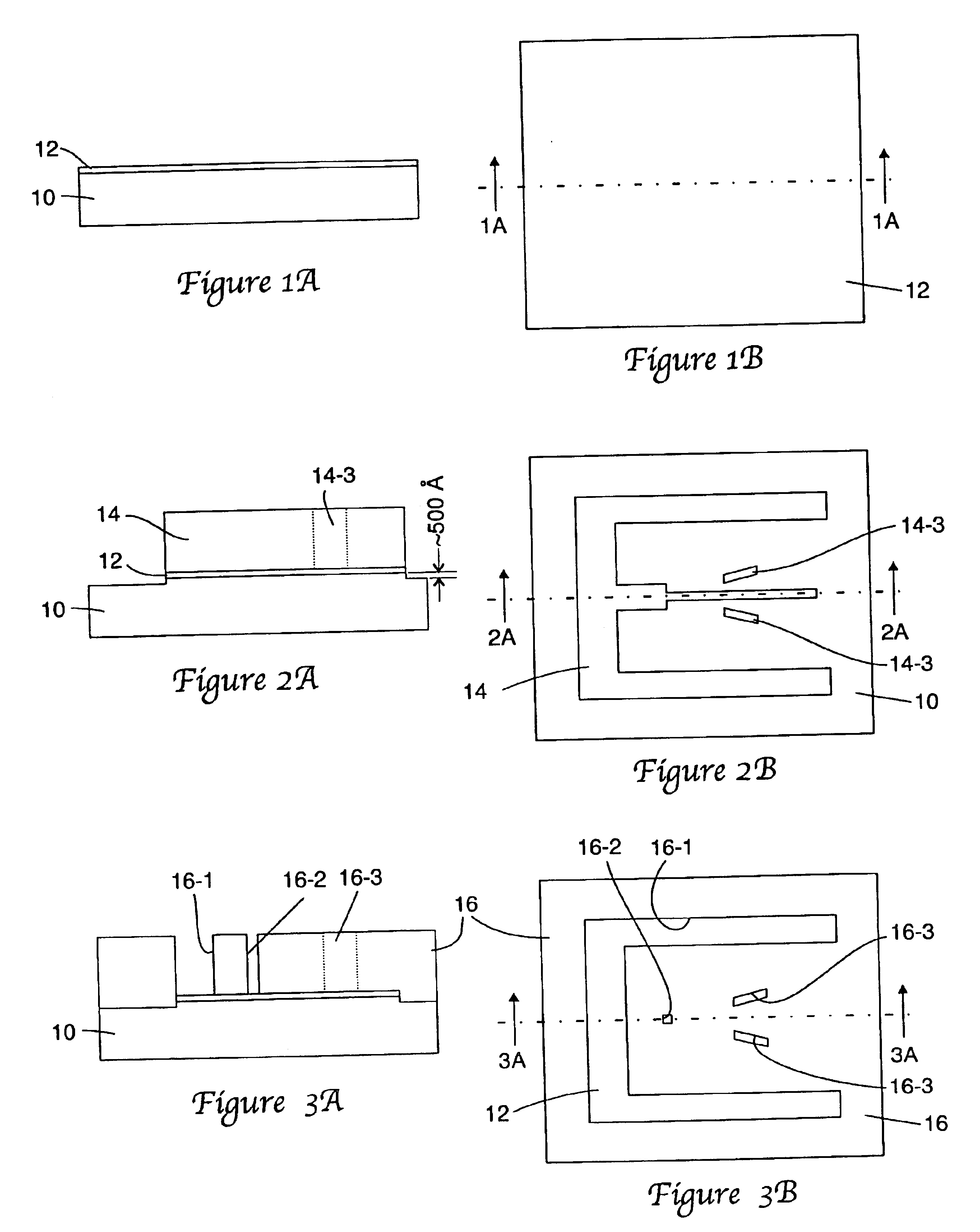
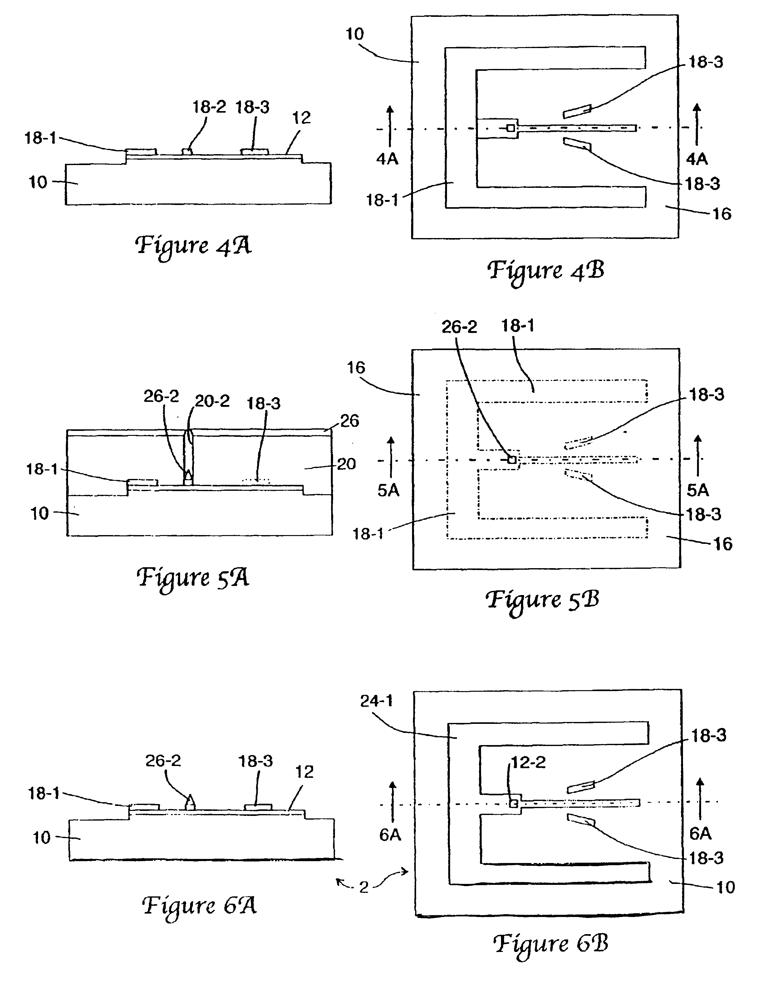
[0009]FIGS. 1A through 6A depict the fabrication of a first embodiment of the cantilevered beam forming portion of a MEM gyroscope;
[0010]FIGS. 1B through 6B correspond to FIGS. 1A-6A, but show the cantilevered beam forming portion, during its various stages of fabrication, in plan view:
[0011]FIGS. 7A through 11A show, in cross section view, the fabrication of the base porti...
PUM
Property
Measurement
Unit
Thickness
aaaaa
aaaaa
Pressure
aaaaa
aaaaa
Concentration
aaaaa
aaaaa
Abstract
A method of making a micro electromechanical gyroscope. A cantilevered beam structure, first portions of side drive electrodes and a mating structure are defined on a first substrate or wafer; and at least one contact structure, second portions of the side drive electrodes and a mating structure are defined on a second substrate or wafer, the mating structure on the second substrate or wafer being of a complementary shape to the mating structure on the first substrate or wafer and the first and second portions of the side drive electrodes being of a complementary shape to each other. A bonding layer, preferably a eutectic bonding layer, is provided on at least one of the mating structures and one or the first and second portions of the side drive electrodes. The mating structure of the first substrate is moved into a confronting relationship with the mating structure of the second substrate or wafer. Pressure is applied between the two substrates so as to cause a bond to occur between the two mating structures at the bonding or eutectic layer and also between the first and second portions of the side drive electrodes to cause a bond to occur therebetween. Then the first substrate or wafer is removed to free the cantilevered beam structure for movement relative to the second substrate or wafer. The bonds are preferably eutectic bonds.
Description
RELATED APPLICATIONS[0002]This application is a divisional of pending prior U.S. patent application Ser. No. 09 / 629,679, filed on Aug. 1, 2000 (now U.S. Pat. No. 6,555,404). This invention is related to other inventions that are the subject of separate patent applications filed thereon. See: U.S. patent application Ser. No. 09 / 629,682, filed on Aug. 1, 2000 (now U.S. Pat. No. 6,580,138) entitled “A Single Crystal, Dual Wafer, Tunneling Sensor or Switch with Silicon on Insulator Substrate and a Method of Making Same,” the disclosure of which is incorporated herein by reference, and a divisional application of that application. U.S. patent application Ser. No. 10 / 358,471, filed Feb. 4, 2003; U.S. patent application Ser. No. 09 / 629,6.84 filed Aug. 1, 2000 entitled “A Single Crystal, Dual Wafer, Tunneling Sensor and a Method of Making Same,” the disclosure of which is incorporated herein by reference, and a divisional application of that application. U.S. patent application Ser. No. 10 / ...
Claims
Application Information
Patent Timeline
Application Date:The date an application was filed.
Publication Date:The date a patent or application was officially published.
First Publication Date:The earliest publication date of a patent with the same application number.
Issue Date:Publication date of the patent grant document.
PCT Entry Date:The Entry date of PCT National Phase.
Estimated Expiry Date:The statutory expiry date of a patent right according to the Patent Law, and it is the longest term of protection that the patent right can achieve without the termination of the patent right due to other reasons(Term extension factor has been taken into account ).
Invalid Date:Actual expiry date is based on effective date or publication date of legal transaction data of invalid patent.