
Deformable mirror with high-bandwidth servo for rigid body control

Inactive Publication Date: 2005-01-11
NIKON CORP
View PDF9 Cites 64 Cited by
  • Summary
  • Abstract
  • Description
  • Claims
  • Application Information

AI Technical Summary

Benefits of technology

It is therefore an object of this invention to provide a method of precisely controlling the rigid body positions of a deformable mirror.
It is still another object of this invention to provide a lithography system incorporating an optical system including such a deformable mirror arrangement and a method of precisely controlling the rigid body positions of its deformable mirror.

Problems solved by technology

These many actuators overconstrain the mirror, and overconstrained mirrors have disadvantages for precision control.

Method used


Image

  • Deformable mirror with high-bandwidth servo for rigid body control
  • Deformable mirror with high-bandwidth servo for rigid body control
  • Deformable mirror with high-bandwidth servo for rigid body control

Examples


Embodiment Construction

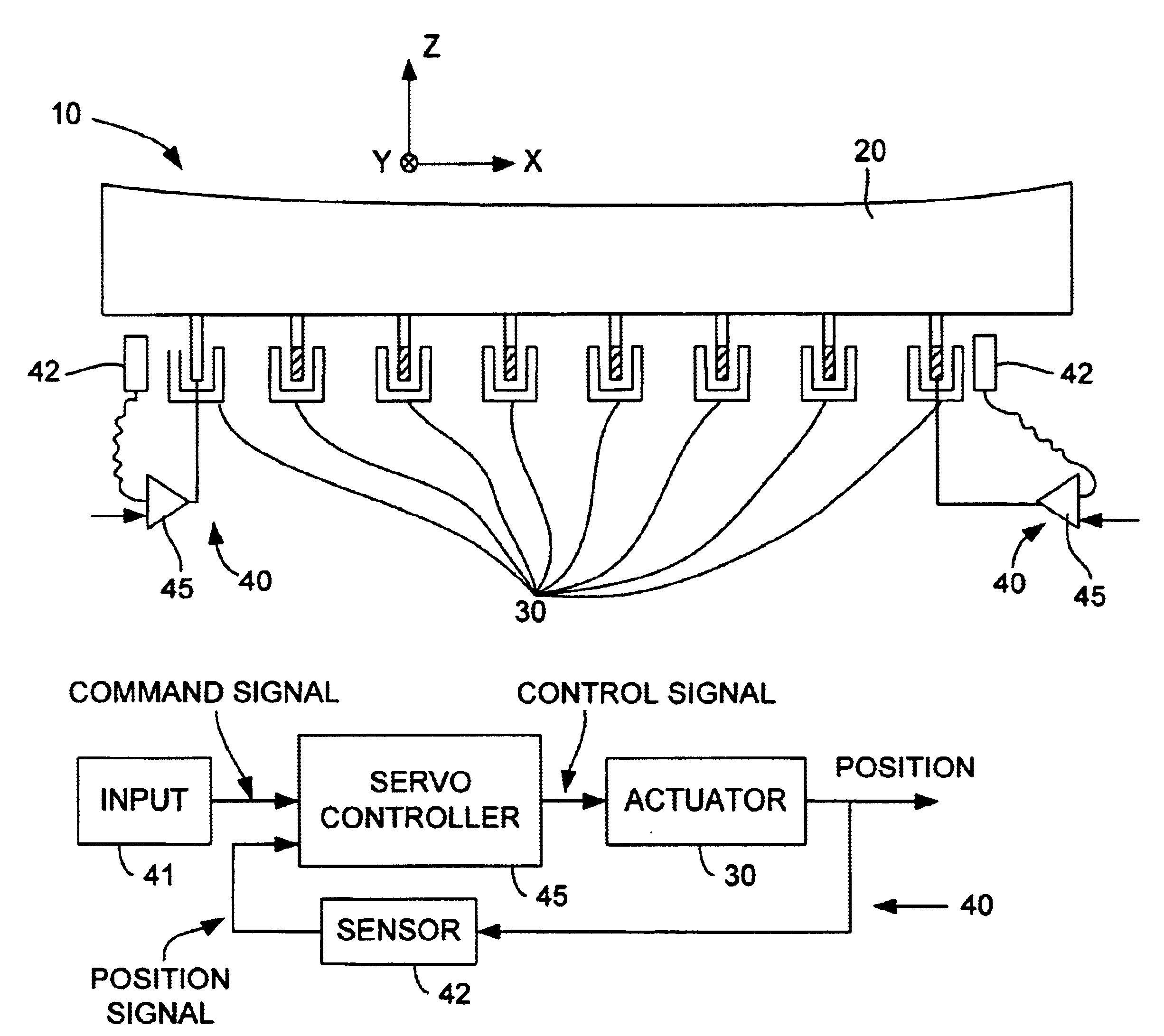
FIG. 4 shows very schematically a deformable mirror arrangement 10 embodying this invention with a deformable mirror 20 supported by many low-stiffness actuators 30 at as many positions on its back surface for locally deforming the mirror 20. These actuators 30 may be passive or actively controlled. Examples of passive actuators include soft springs of which preload is adjusted with screws or other position actuators. Examples of actively controlled force actuators include voice coil motors (VCMs), pneumatic actuators and EI-core actuators.

Some or all of the six rigid-body degrees of freedom of the mirror 20 are controlled by high-bandwidth servos-controlled actuators. For the convenience of illustration, FIG. 4 shows only two high-bandwidth servos 40 but the mirror arrangement 10 according to this invention include at least three high-bandwidth servos 40 for adjusting at least three rigid body positions. Each of the at least three high-bandwidth servos 40 includes one of the active...


PUM


Abstract

A deformable mirror arrangement has a plurality of constraint mechanisms contacting a deformable mirror at specified contact positions. At least three of these constraint mechanisms are rigid body servo control mechanisms such as high-bandwidth servo control mechanisms, each including a force actuator contacting the mirror at a corresponding one of the contact positions, a position sensor assisting to measure position of the mirror and a servo control unit for controlling the force actuator.

Description

BACKGROUND OF THE INVENTIONThis invention is in the technical field of rigid body control of a deformable mirror and more particularly to rigid body control of a deformable mirror with high-bandwidth servo.It has been known to support a deformable mirror, and more particularly a thin-membrane mirror, by means of many high-stiffness actuators such as PZT actuators, as described, for example, in U.S. Pat. No. 5,037,184 issued Aug. 6, 1991 to Ealey. These many actuators overconstrain the mirror, and overconstrained mirrors have disadvantages for precision control.Deformable mirrors with low-stiffness force-type actuators for controlling deformation without overconstraint were disclosed by John Hardy (“Active Optics: A New Technology for the Control of Light,” IEEE, Vol. 60, No. 6 (1978)) but high-stiffness kinematic mounts are used for controlling the position in six degrees of freedom. Kinematically constrained deformable mirrors with force actuators require some other means for contr...

Claims


Application Information

Patent Timeline
IPC IPC(8): G02B26/08G03F7/20G02B7/182G02B5/10G02B7/198G02B17/00H01L21/027
CPCG02B7/182G03F7/70266G02B26/0825
Inventor WATSON, DOUGLAS C.
Owner NIKON CORP
Learn More