The present invention, therefore, seeks to improve the state of the art, by creating lenticular display devices, which combine all of the following aspects: (1) proper choice of a moving element; (2) fine control of motion by a user-friendly interface, between the print and overlaying screen; (3)
close contact between the print and overlaying screen; (4) reduction of friction between print and screen, for either pre-printed (applied during manufacture), or computer-printer images (
consumer-applied); (5) ease of image replacement; (6)
accommodation of standard, computer printer media sizes; (7) a low cost
software for mastering and printing of lenticular images with widely available computers and printers, as well as a
file format which includes pertinent information to a lenticular file, such as lenses per inch, and number of compressed images; and (8) ease of adjusting co-
linearity between print and screen.
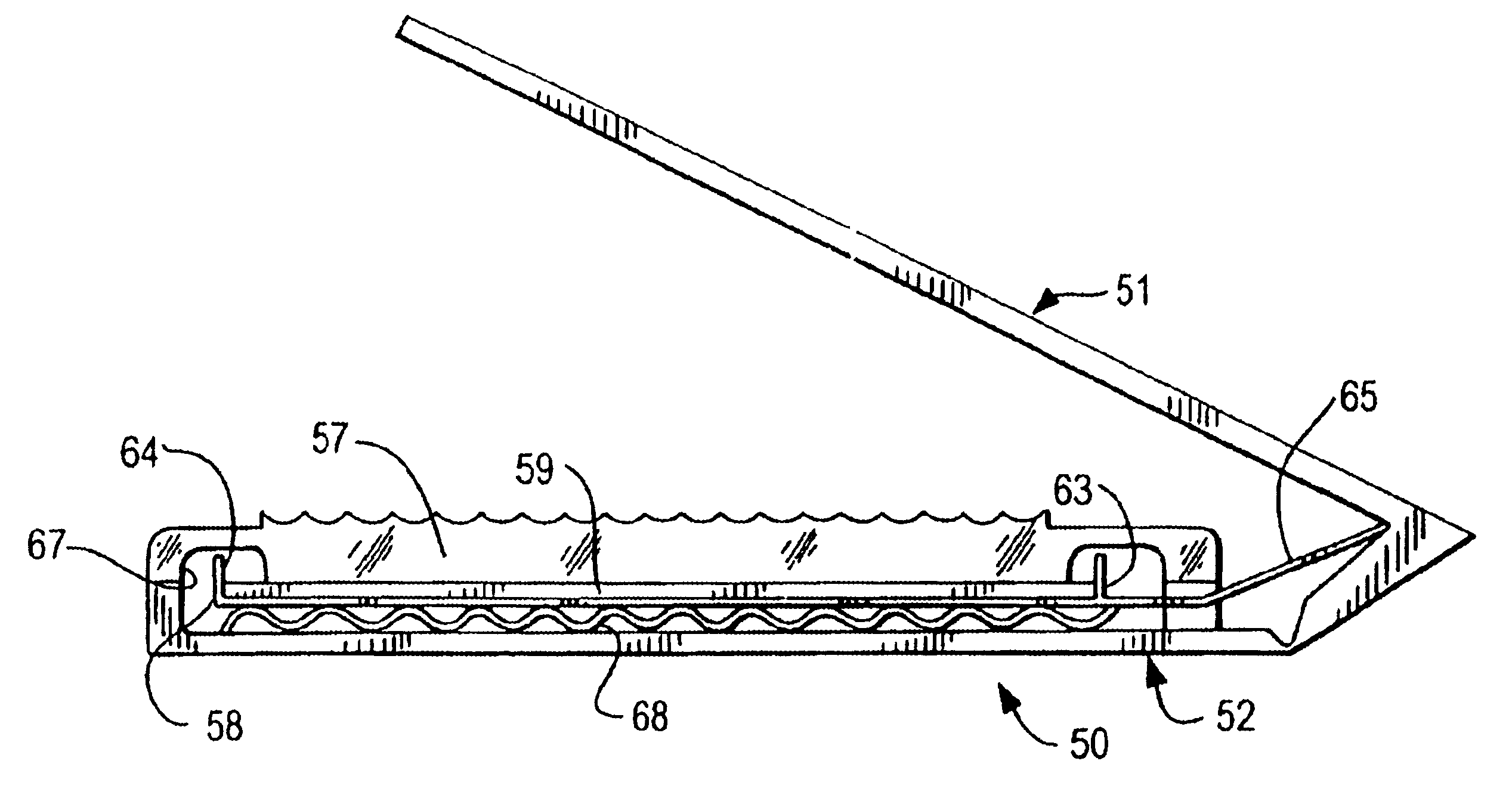
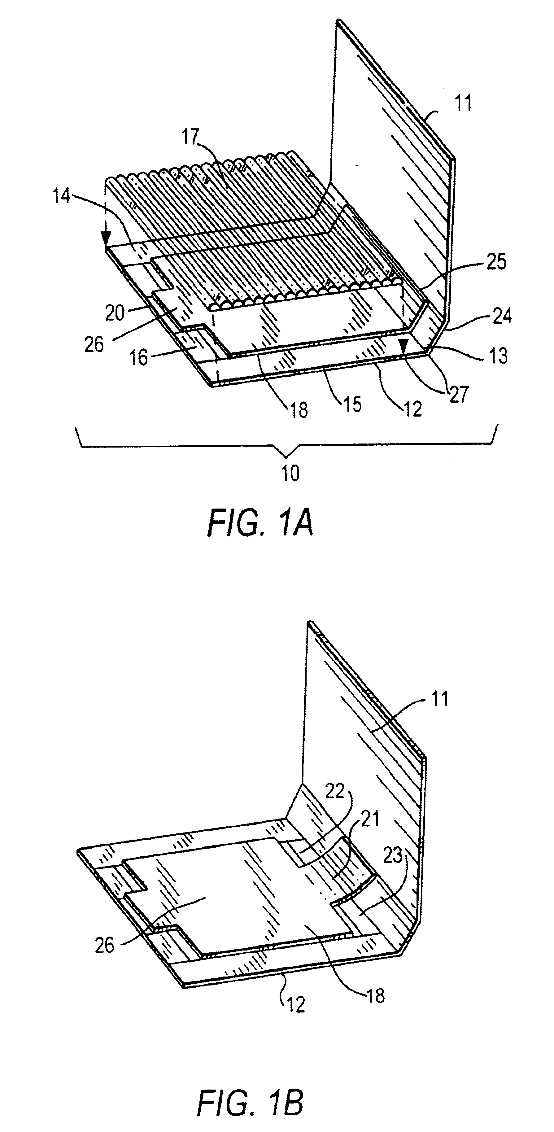
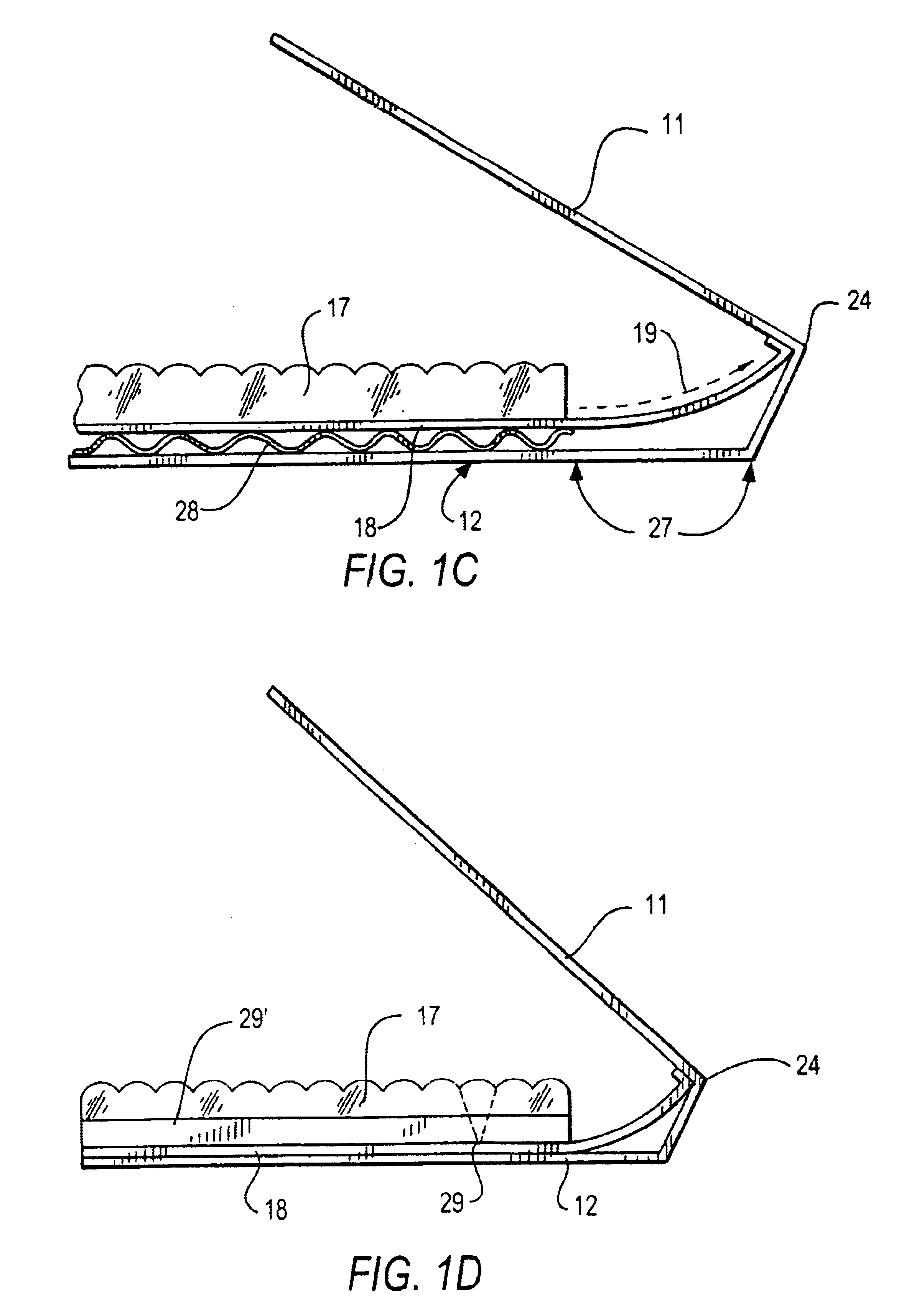
In any of the book, card-case, or folding card embodiments, the hinged cover may translate its motion at right angles, so as to be opened from the left or right, and not interfere with the light illuminating the card interior. The hinged cover may be made by other means, including injection-molding, as well as
die cutting. The cover can also be made transparent, or removable, thereby leaving a smaller plane or stick that interferes with less light than the cover would when held half open and in the case of the book, operates in a less cumbersome manner than by
flapping the whole cover. If the cover is removed and a smaller plane 8 is used, it need only be as large as the section between the print / tray and the bottom flap, and may be duplicated at the opposite end of the bottom flap, forming a
parallelogram comprised of the two opposing small planes, and the larger planes of the print / tray and the bottom flap, thereby greatly enhancing the straightness of motion of the print / tray. This is especially useful with larger images, and facilitates motorization. Also, the screen may cover only a portion of the entire page, which may protrude from the book, or a portion of the screen may be left clear, with no lenticules, so that a copy may be easily read from the page. Either the replaceable, or non-replaceable folding cards may be made with their back flap translucent or transparent to accommodate transparent images.
A
software application to create lenticular images consists of a method to choose any number of image files, from drive and
directory, and a method to enter the chosen images into an image
list, such as double clicking the
computer mouse. As each image's filename is entered into an image
list, an on-screen image box displays the current image. As the mouse is moved with its left button held down over each filename in the image
list, that image is displayed in the image box, creating a sequential display very helpful in assessing how well the images will look when merged, whether for
animation, 3D, or other types of images. Images may be removed from any spot in the image list without leaving a gap.
Once aligned, some parts of the images may not be needed, so a
cropping feature is included, so as not to show the unwanted areas, and to save file space.
The software also allows choice of lenses per inch, pixels per inch of the final, merged image, and the final, merged image size. To make the program easier to use, the final pixels per inch are computed automatically by multiplying the number of lenses per inch by the number of images, and that product is suggested to use as an appropriate choice for the pixels per inch number. Should the user choose another number for pixels per inch, a warning will be displayed, saying that to use less than the suggested number may degrade the
image quality, but leaving the option to enter any number. Should the user attempt to merge the images without entering a number for lenses per inch or number of images, a reminder will show on-screen to enter these numbers.

