Pump drive head with stuffing box

a technology of drive head and stuffing box, which is applied in the direction of drilling casings, drilling pipes, borehole/well accessories, etc., can solve the problems of significant safety hazards, and achieve the effect of removing belt tensioning and replacing

Inactive Publication Date: 2005-01-18
OIL ELEVATOR TECH
View PDF13 Cites 107 Cited by
  • Summary
  • Abstract
  • Description
  • Claims
  • Application Information

AI Technical Summary

Benefits of technology

The present invention seeks to address all these issues and combines all functions into a single drive head. The drive head of the present invention eliminates the conventional belts and sheaves that are used on all drives presently on

Problems solved by technology

Elimination of belts and sheaves removes a significant safety hazard that arises due t

Method used


Image

  • Pump drive head with stuffing box
  • Pump drive head with stuffing box
  • Pump drive head with stuffing box

Examples


Embodiment Construction

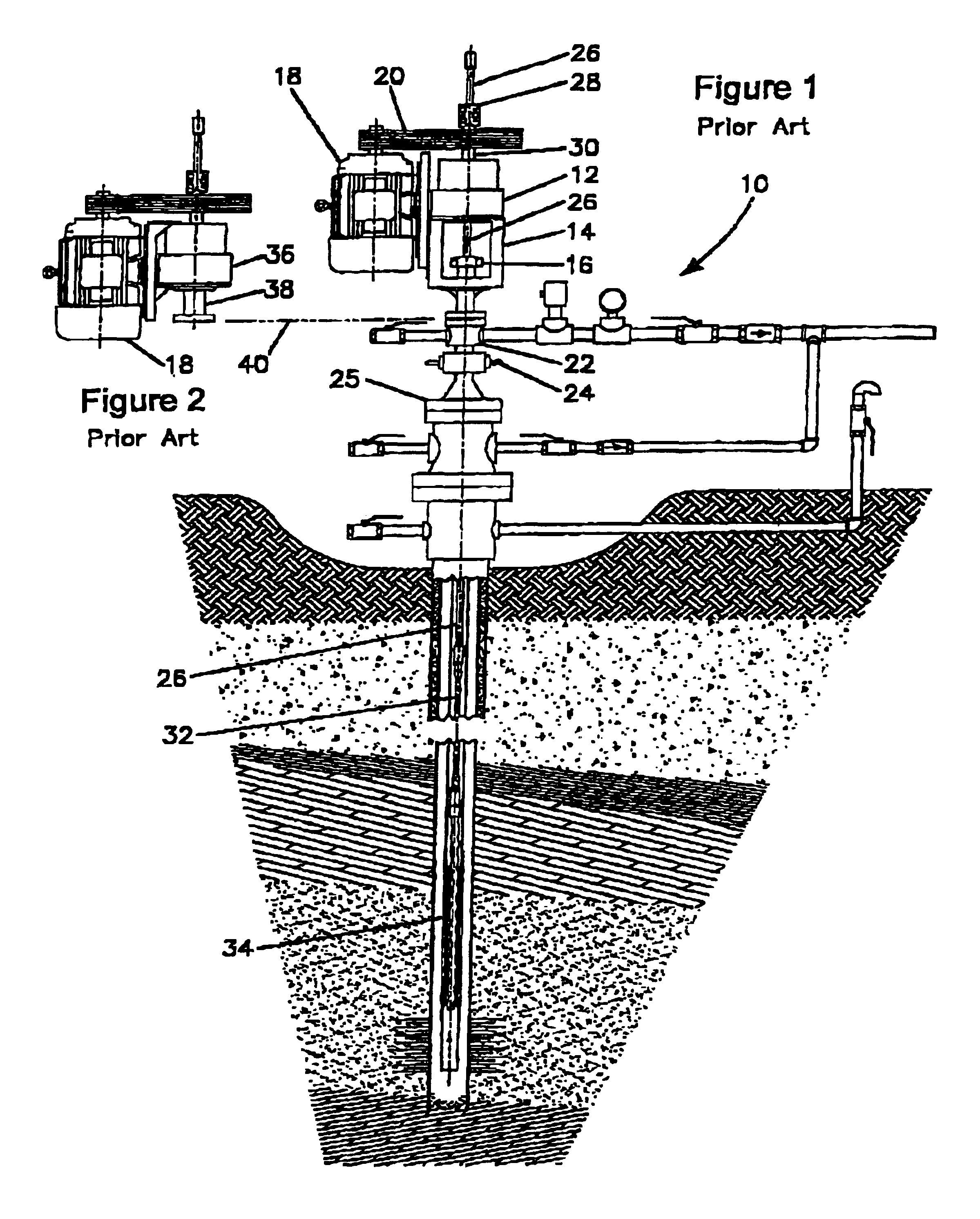
FIG. 1 illustrates a known progressing cavity pump installation 10. The installation includes a typical progressing cavity pump drive head 12, a wellhead frame 14, a stuffing box 16, an electric motor 18, and a belt and sheave drive system 20, all mounted on a flow tee 22. The flow tee is shown with a blow out preventer 24 which is, in turn, mounted on a wellhead 25. The drive head supports and drives a drive shaft 26, generally known as a “polished rod”. The polished rod is supported and rotated by means of a polish rod clamp is 28, which engages an output shaft 30 of the drive head by means of milled slots (not shown) in both parts. Wellhead frame 14 is open sided in order to expose polished rod 26 to allow a service crew to install a safety clamp on the polished rod and then perform maintenance work on stuffing box 16. Polished rod 26 rotationally drives a drive string 32, sometimes referred to as “sucker rods”, which, in turn, drives a progressing cavity pump 34 located at the b...


PUM


Abstract

A pump drive head for a progressing cavity pump comprises a top mounted stuffing box rotatably disposed around a compliantly mounted standpipe with a self or manually adjusting pressurization system for the stuffing box. To prevent rotary and vertical motion of the polish rod while servicing the stuffing box, a polished rod lock-out clamp is provided with the pump drive head integral with or adjacent to a blow-out-preventer which can be integrated with the pump drive head to save space and cost. A centrifugal backspin braking system located on the input shaft and actuated only in the backspin direction and a gear drive between the input shaft and output shaft are provided.

Description

FIELD OF THE INVENTIONThe present invention relates generally to progressing cavity pump oil well installations and, more specifically, to a drive head for use in progressing cavity pump oil well installations.BACKGROUND OF THE INVENTIONProgressing cavity pump drives presently on the market have weaknesses with respect to the stuffing box, backspin retarder and the power transmission system. Oil producing companies need a pump drive which requires little or no maintenance, is very safe for operating personnel and minimizes the chances of product leakage and resultant environmental damage. When maintenance is required on the pump drive, it must be safe and very fast and easy to do.Due the abrasive sand particles present in crude oil and poor alignment between the wellhead and stuffing box, leakage of crude oil from the stuffing box is common in some applications. This costs oil companies money in service time, down time and environmental clean up. It is especially a problem in heavy ...

Claims


Application Information

Patent Timeline
IPC IPC(8): E21B43/12
CPCE21B43/126E21B33/085Y10T403/7062E21B33/03E21B19/00E21B33/08
Inventor HULT, VERN A.
Owner OIL ELEVATOR TECH
Why Eureka
Try Eureka