Fuel driven setting tool

a technology of setting tool and fuel, which is applied in the direction of manufacturing tools, nailing tools, stapling tools, etc., can solve the problems of having to recharge the nicd storage battery by an external energy source, and being relatively inconvenient for users

Active Publication Date: 2005-01-18
HILTI AG
View PDF6 Cites 32 Cited by
  • Summary
  • Abstract
  • Description
  • Claims
  • Application Information

AI Technical Summary

Benefits of technology

h permanent magnets are arranged on one wall of the combustion chamber facing t...

Problems solved by technology

The drawback is that the NiCd storage battery must be recharged by an external energy source.
The ...

Method used


Image

  • Fuel driven setting tool
  • Fuel driven setting tool
  • Fuel driven setting tool

Examples


first embodiment

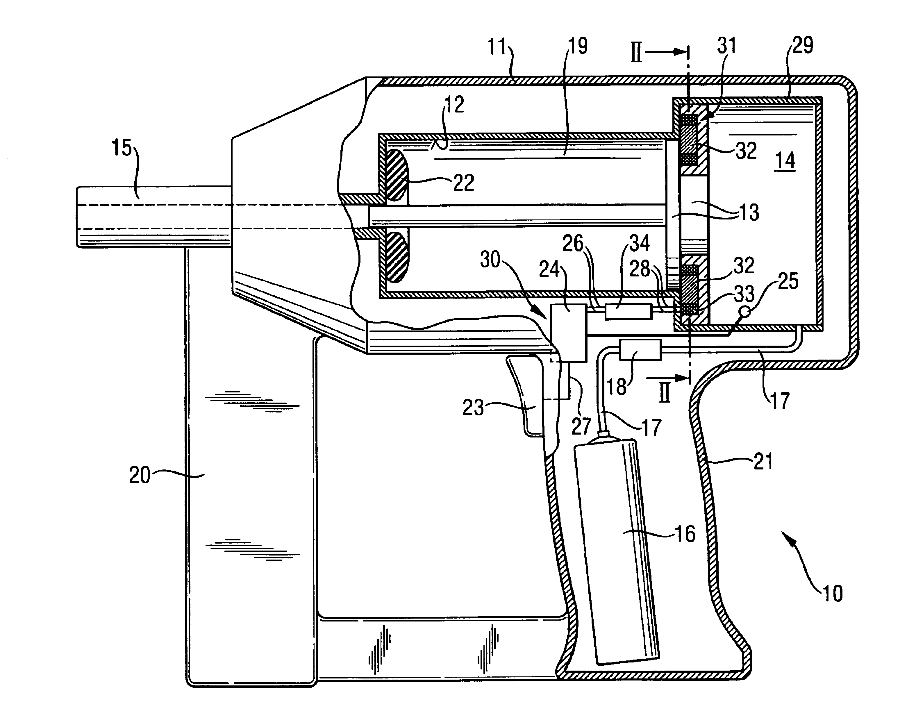
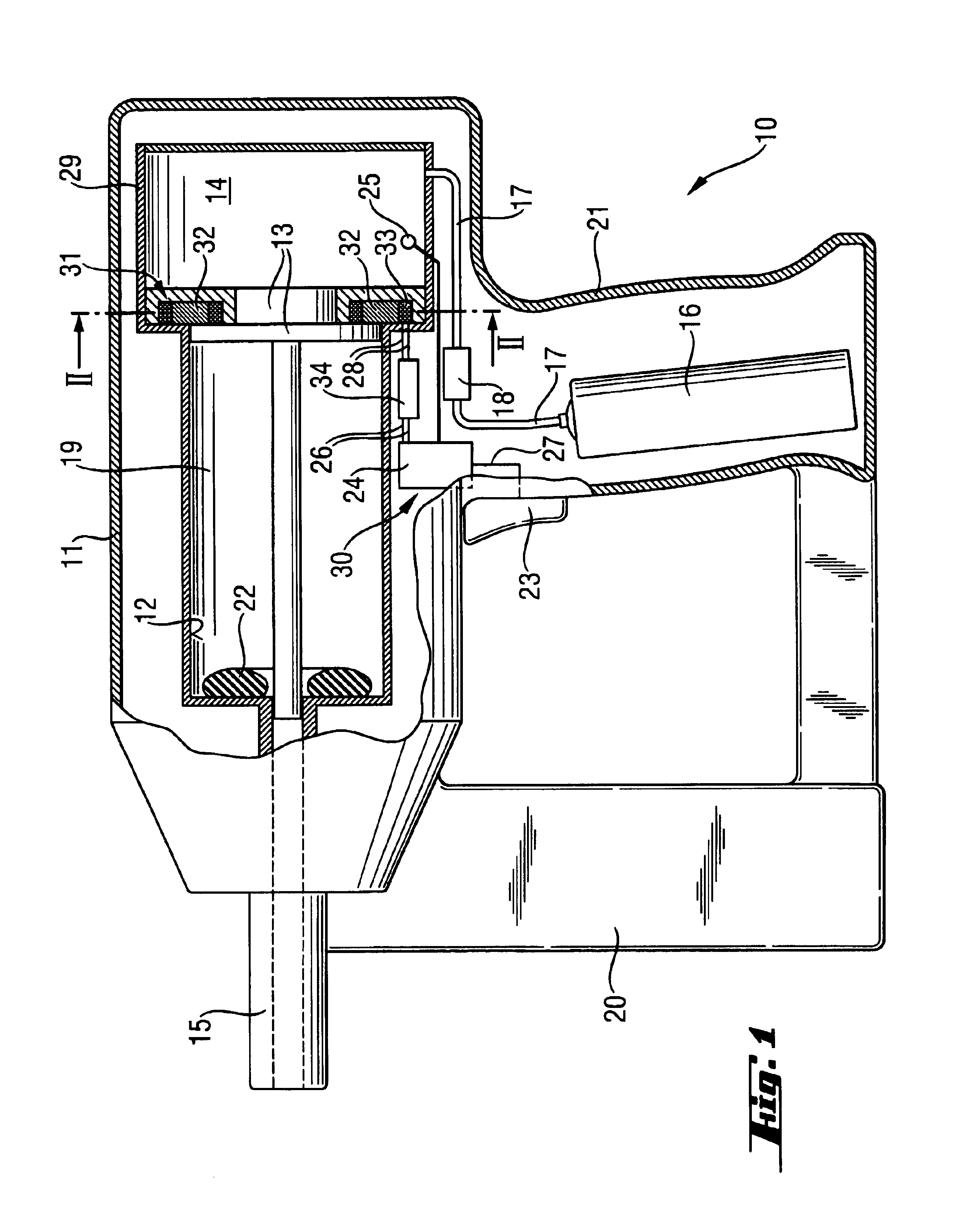
[0022]In FIGS. 1 to 3, a setting tool 10 according to the invention is shown in its resting or starting position. The setting tool 10 has a single piece or multipart housing part, generally identified using 11, in which the setting mechanism is arranged. Using the setting tool, a fastener such as a nail, bolt, etc. can be driven into a substrate (not shown), when the setting tool 10 is pressed onto a substrate with its bolt guide 15 and fired.

[0023]The setting mechanism comprises a combustion chamber 14, a piston guide 12, in which a setting piston 13 is axially displaceable and a bolt guide 15, in which a fastener can be guided and where a fastener, during a setting operation, moves over the forward advancing, setting end of the setting piston 13 or its piston rod and can be driven into a substrate. When this is done, the bolt guide 15 makes contact at the piston guide 12 in the setting direction. In the forward end region of the piston guide 12, additional damping elements 22 are ...

second embodiment

[0027]In FIGS. 4 to 5, a setting tool 10 according to the invention is shown in its resting or starting position. The setting tool differs from the setting tool shown in FIGS. 1 to 3 in that the electrical energy is supplied by a differently configured generator device 40. While in generator device 30 of FIGS. 1 to 3, kinetic setting energy is converted to electrical energy and thus the thermal energy is released at the time of combustion, the propellant is used by the generator device 40 for the production of electrical energy.

[0028]The generator device 40 includes an arrangement 41 of Peltier elements 42, that is arranged external to the combustion chamber 14 on a combustion chamber wall 29 and which produces electrical energy from the heat Q generated at the time of combustion in the combustion chamber 14. In this instance, the Peltier elements 42 are arranged in layers that are separated from each other by insulators 43. A cooling element 50 is arranged on a side of the arrangem...


PUM


Abstract

The present invention relates to a fuel-driven setting tool (10) for driving fastener elements such as nails, bolts, and pins into a substrate. The tool has a setting piston (13) guided in a piston guide (12) and displaceable using the combustion energy of a propellant and having a voltage source for supplying an electrical consumer on the setting tool (10). For improving a setting tool of this type, a generator device (30, 40) can be provided for transforming setting energy from the combustion of the propellant into electrical energy.

Description

BACKGROUND OF THE INVENTION[0002]The present invention relates to a fuel-driven setting tool for driving fastener elements such as nails, bolts, pins and the like into a substrate. The setting tool has a setting piston guided in a piston guide, is displaceable using the combustion energy of a propellant, and has a voltage source for supplying electrical consumers on the setting tool. Such setting tools can be driven using gaseous, vaporizable fluids or solid fuels. A setting piston is driven, in the fuel-driven setting tools, in the setting operation by combustion gases. The fastening elements can be driven into a substrate by the setting piston. Thermal energy is produced, in the setting operation with the kinetic energy of the moving setting piston, which, if required, is diverted over a cooling system, such as cooling ribs or fins etc. to the environment.[0003]Setting tools of this type generally comprise electronic components such as electronically controlled valves, ignition sy...

Claims


Application Information

Patent Timeline
IPC IPC(8): B25C1/08
CPCB25C1/08
Inventor FAVRE-BULLE, BERNARD
Owner HILTI AG
Why Eureka
Try Eureka