Method for removing metal cladding from airfoil substrate

a metal cladding and airfoil technology, applied in the direction of liquid fuel engines, efficient propulsion technologies, machines/engines, etc., can solve the problems of reducing the performance of compressors, reducing the service life of compressors, and reducing the malleability of metal cladding, so as to reduce or eliminate damage

Inactive Publication Date: 2005-01-18
GENERAL ELECTRIC CO
View PDF25 Cites 30 Cited by
  • Summary
  • Abstract
  • Description
  • Claims
  • Application Information

AI Technical Summary

Benefits of technology

The method of the present invention provides a number of significant benefits over prior mechanical methods for removing such metal cladding adhered to the substrate of an airfoil, especially turbine blade. The method of the present invention reduces or eliminates the damage that can be caused by prying or peeling away the cladding from the substrate using a mechanical tool. The method of the present invention is particularly advantageous where the metal cladding to be removed is relatively strong and less malleable. It is also advantageous where the metal cladding is adhered to the substrate at or along an edge (e.g., leading edge) having a compound series of curves and / or where the metal cladding varies in thickness from the interior of the exposed airfoil or blade surface (e.g., relatively thin) to the perimeter of the edge (e.g., relatively thick).

Problems solved by technology

Composite blades are susceptible to foreign object damage.
Smaller objects can erode the blade material and degrade the performance of the compressor.
Impact by larger objects can rupture or pierce the blades with portions of an impacted blade being torn loose and causing extensive secondary damage to downstream blades and other engine components.
The vulnerability of these composite blades to foreign object damage is due to two factors.
First, the lightweight matrix material employed for the substrate of the blade, such as polymeric resins or aluminum, can be susceptible to erosion.
Second, when high strength filaments are used, these materials can be relatively brittle compared to metals and metal alloys, such as titanium.
Even this metal cladding adhered to the edges of the turbine fan blade can become dented and damaged due to foreign objects, and thus require repair or replacement.
Unfortunately, as the metal cladding is peeled away, it can strip off or otherwise damage the underlying composite substrate.
In addition, metal claddings that are relatively strong and less malleable can tear (rather than bend) during this peeling operation, making it more difficult to remove the cladding.

Method used


Image

  • Method for removing metal cladding from airfoil substrate
  • Method for removing metal cladding from airfoil substrate
  • Method for removing metal cladding from airfoil substrate

Examples


Embodiment Construction

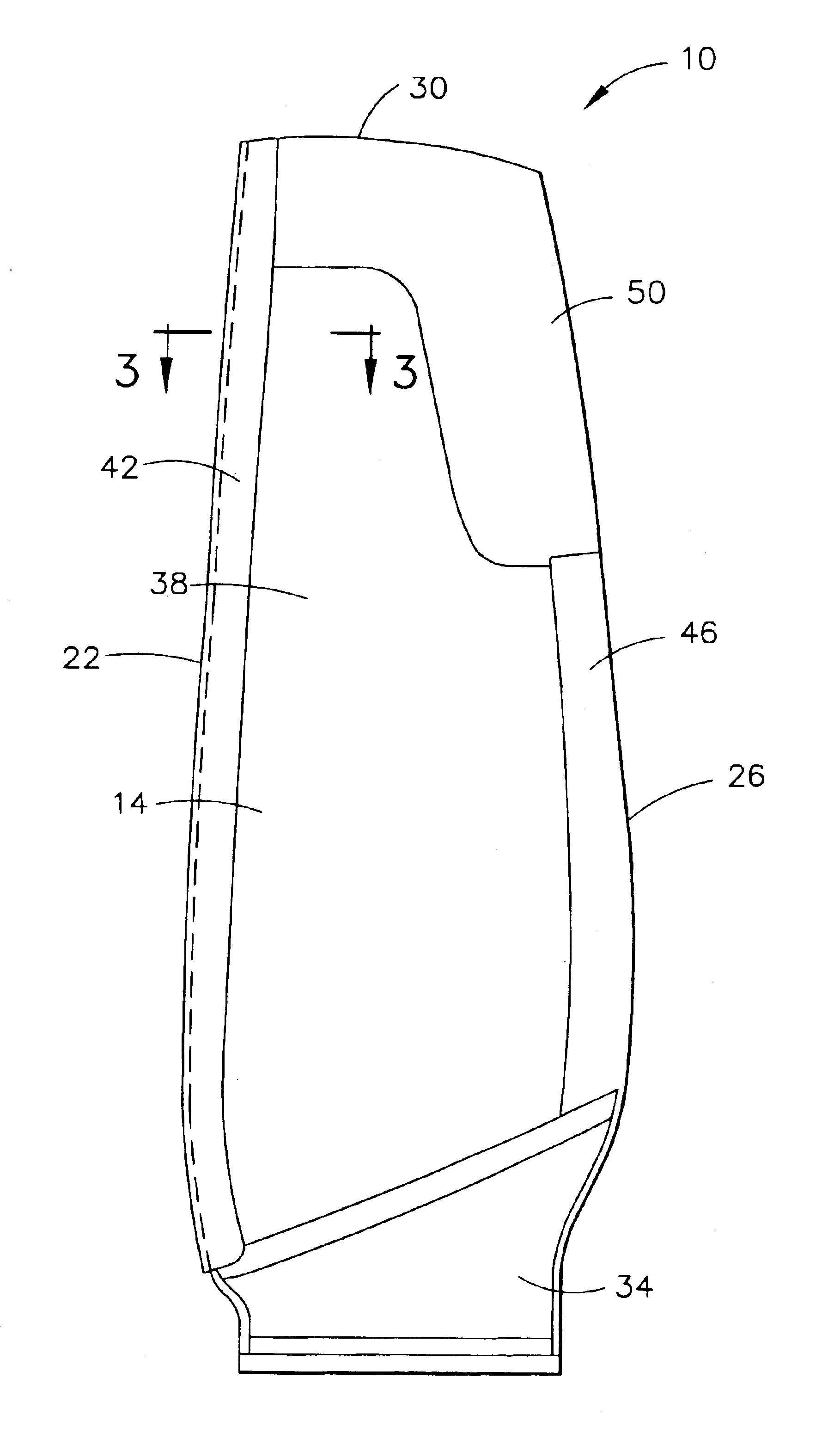
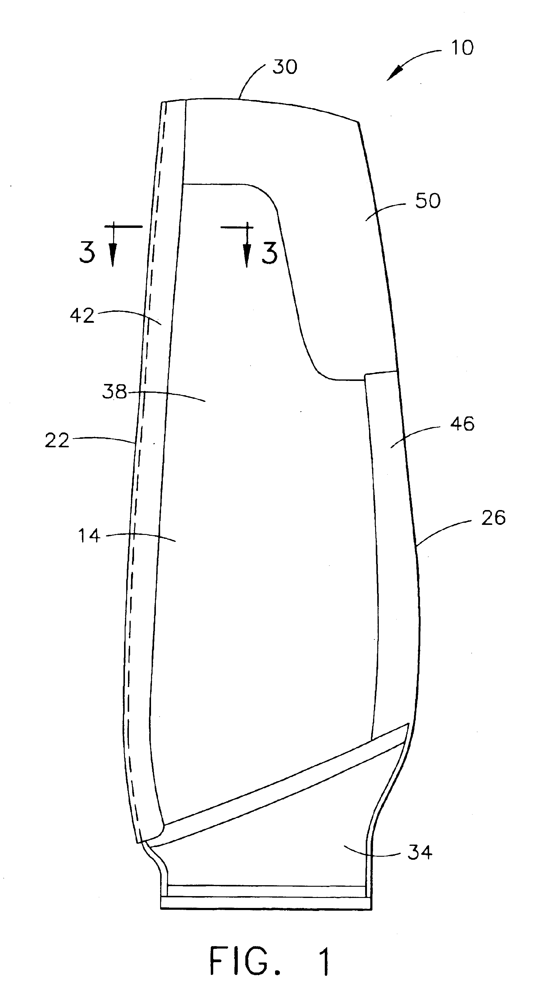
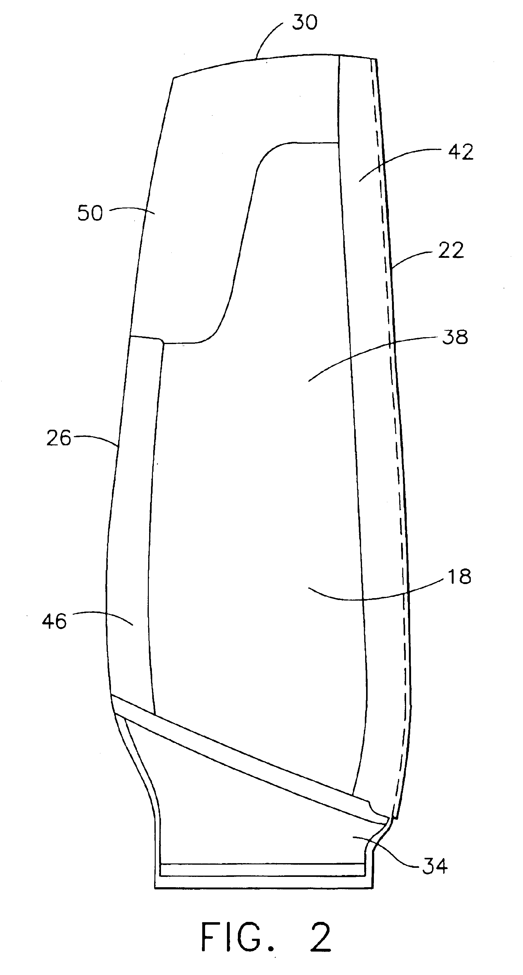
Referring to the drawings, FIGS. 1 and 2 show different sides of a representative gas turbine engine fan blade for which the method of the present invention can be useful that is indicated generally as 10. While the description of the method of the present invention is with reference to a turbine fan blade, it should be understood that this method is applicable to other airfoils, including vanes, propellers, rotor blades (e.g., for helicopters), as well as other types of turbine blades that have metal cladding that is adhered to a substrate. FIG. 1 shows the convex curved surface of blade 10 (also referred to as the “suction” side of the blade) indicated generally as 14, while FIG. 2 shows the concave curved surface of blade 10 (also referred to as the “pressure” side of the blade) indicated generally as 18. Blade 10 also has a leading edge indicated as 22, a trailing edge indicated as 26, a tip edge indicated as 30 and a blade root indicated as 34.

The substrate portion of blade 10 ...


PUM

PropertyMeasurementUnit
thicknessaaaaaaaaaa
thicknessaaaaaaaaaa
thicknessaaaaaaaaaa

Abstract

A method for removing metal cladding adhered to an airfoil, such as a turbine blade, wherein the airfoil comprises a substrate and wherein at least a portion of the cladding is adhered to at least one surface of the substrate of the airfoil. In this method the cladding is treated with a chemical etchant of the metal that the cladding is made of for a period of time sufficient to remove at least the portion of the cladding adhered to the at least one surface of the substrate. The substrate is made of a material that is chemically resistant to the etchant.

Description

BACKGROUND OF THE INVENTIONThe present invention relates generally to a method for removing metal cladding that is adhered to at least one surface of the substrate of an airfoil, such as a turbine (fan) blade, by treating the metal cladding with a chemical etchant. The present invention particularly relates to a method for removing titanium cladding that is adhered at or along the leading edge of the substrate of an airfoil, such as a turbine blade, to a non-metallic fiber reinforced resin substrate by treating the titanium cladding with a chemical etchant that comprises hydrofluoric acid.High bypass turbofan engines are widely used for high performance aircraft that operate at subsonic speeds. Large fans are typically placed at the front of such engines, and serve to produce greater thrust and reduce specific fuel consumption. To minimize engine weight while optimizing performance, it is often preferred to incorporate a maximum number of fan blades having a fixed root blade configu...

Claims


Application Information

Patent Timeline
Patent Type & Authority Patents(United States)
IPC IPC(8): C23F1/26C23F1/10C23F1/44F01D5/00F01D5/28F01D25/00F02C7/00F04D29/38
CPCC23F1/26C23F1/44F01D5/005F05D2230/80Y02T50/672F05D2230/90F04D29/324F05D2240/303Y02T50/60
Inventor CLINE, LARRY DEANPAULEY, GERALD ALEXANDER
Owner GENERAL ELECTRIC CO
Why Eureka
Try Eureka