High performance heat sink configurations for use in high density packaging applications

a heat sink and high-performance technology, applied in the direction of insulated conductors, lighting and heating apparatus, cables, etc., can solve the problems of increasing the amount of heat generated by components, increasing the packaging densities and amounts, and increasing the footprint of the heat sink

Inactive Publication Date: 2005-01-18
INTEL CORP
View PDF56 Cites 18 Cited by
  • Summary
  • Abstract
  • Description
  • Claims
  • Application Information

AI Technical Summary

Problems solved by technology

Integrated circuit devices, microprocessors and other related computer components are becoming more and more powerful with increasing capabilities, resulting in increasing packaging densities and amounts of heat generated from these components.
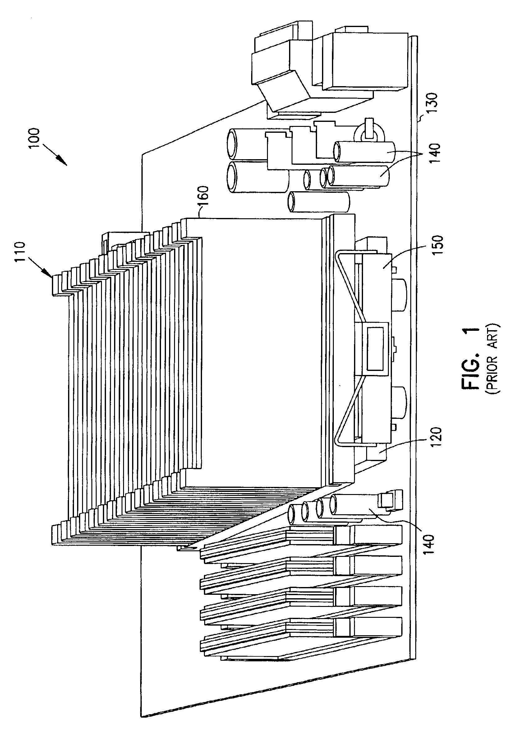
The flat base plate of the heat sink has a large footprint.
The large footprint requires more motherboard real estate than the integrated circuit device in contact therewith.
This results in the outermost part of the heat sink that is not directly in contact with the integrated circuit being less efficient in dissipating heat into the cooling air.
Furthermore, as computer-related equipment becomes more powerful, more components are being placed inside the equipment and on the motherboard which further requires more motherboard real estate.
Consequently, the flat base plate configuration of the heat sink generally ends up consuming more motherboard real estate than the integrated circuit device on which it is mounted.

Method used


Image

  • High performance heat sink configurations for use in high density packaging applications
  • High performance heat sink configurations for use in high density packaging applications
  • High performance heat sink configurations for use in high density packaging applications

Examples


Embodiment Construction

In the following detailed description of the embodiments, reference is made to the accompanying drawings that illustrate embodiments of the present invention and its practice. In the drawings, like numerals describe substantially similar components throughout the several views. These embodiments are described in sufficient detail to enable those skilled in the art to practice the embodiments of the invention. Other embodiments may be utilized and structural, logical, and electrical changes may be made without departing from the scope of the present disclosure. Moreover, it is to be understood that the various embodiments of the invention, although different, are not necessarily mutually exclusive. For example, a particular feature, structure, or characteristic described in one embodiment may be included in other embodiments. The following detailed description is, therefore, not to be taken in a limiting sense, and the scope of the embodiments of the present invention is defined only...


PUM


Abstract

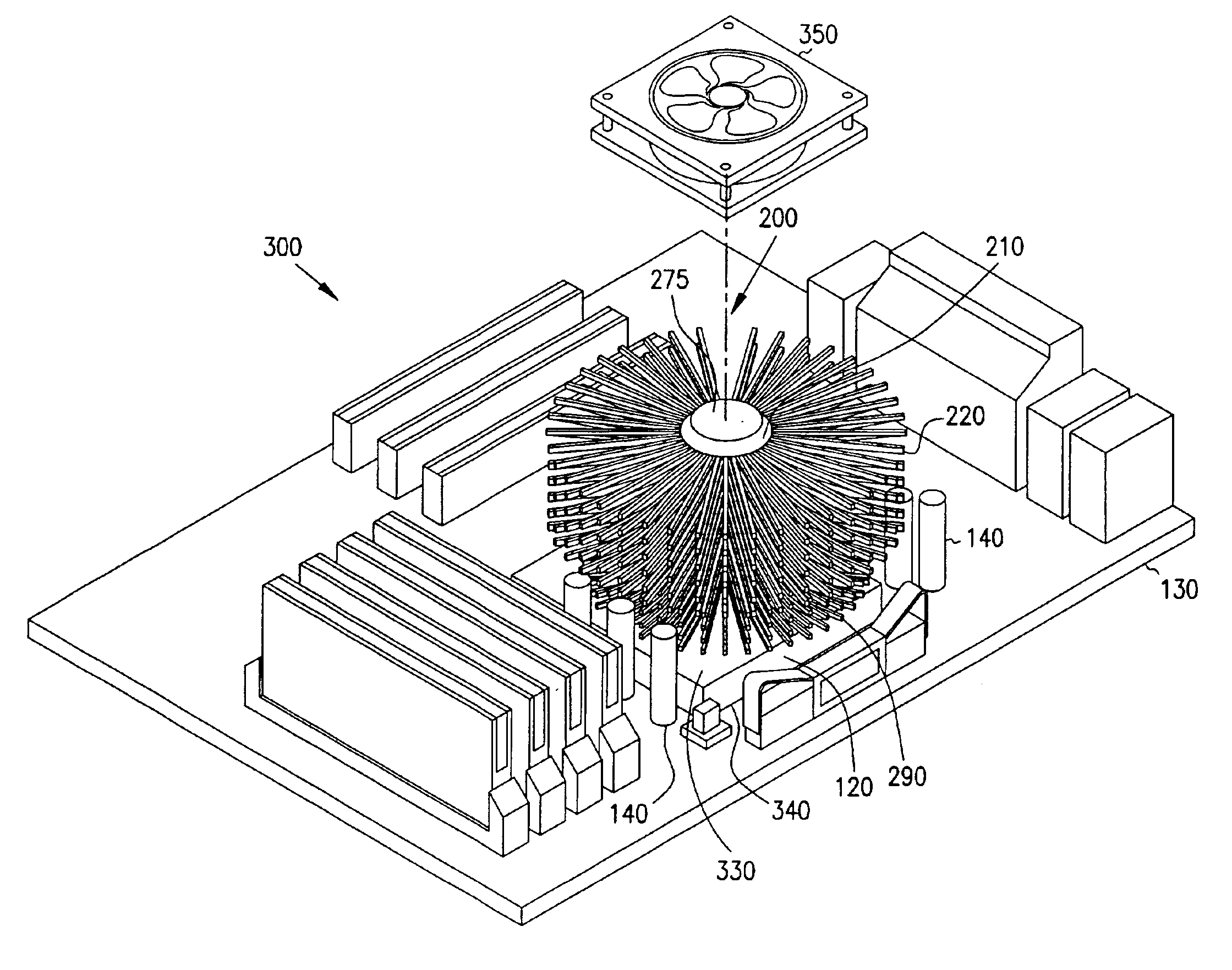
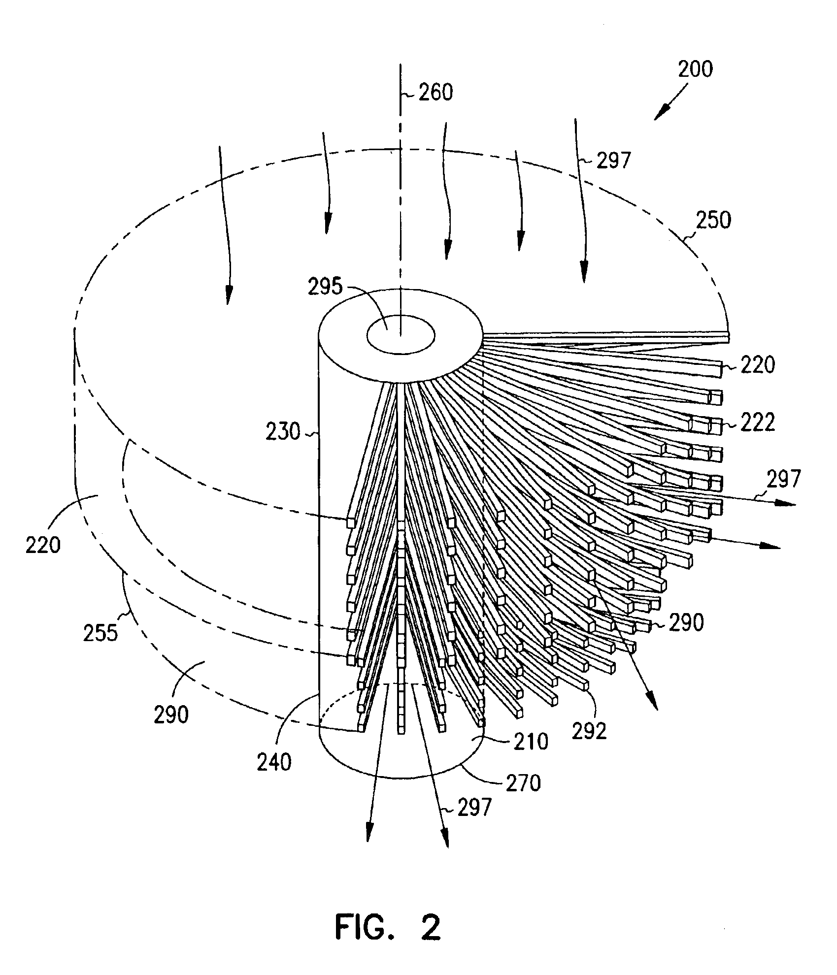
An enhanced heat dissipation device to extract heat from an integrated circuit device includes a thermally conductive core having upper and lower outer surface areas. The device further includes a first array of radially extending pin fin structures. The first array is thermally coupled to the upper surface area such that a cooling medium introduced around the core and the first array creates an omni-directional flow around the first array and the core to enhance heat dissipation from the integrated circuit device. The core including the first array and the lower surface area are of sufficient size to allow components on a motherboard to encroach onto the integrated circuit device when the heat dissipation device is mounted onto the integrated circuit device.

Description

TECHNICAL FIELDThis invention relates generally to a heat dissipation system and method for an integrated circuit assembly, and more particularly to a system and method of dissipating heat from an integrated circuit device.BACKGROUNDIntegrated circuit devices, microprocessors and other related computer components are becoming more and more powerful with increasing capabilities, resulting in increasing packaging densities and amounts of heat generated from these components. Packaged units and integrated circuit device sizes of these components are decreasing or remaining the same, but the amount of heat energy given off by these components per unit volume, mass, surface area or any other such metric is increasing. In current packaging techniques, heat sinks typically consist of a flat base plate, which is mounted onto the integrated circuit device on one side. The heat sinks further include an array of fins running perpendicular to the flat base plate on the other side. Generally, th...

Claims


Application Information

Patent Timeline
Patent Type & Authority Patents(United States)
IPC IPC(8): H01L23/467H01L23/367H01L23/34H05K7/20H01L23/36
CPCH01L23/3672H01L23/3677H01L23/467H01L2924/0002H01L2924/00
Inventor LEE, SERI
Owner INTEL CORP
Why Eureka
Try Eureka