System and method for controlling a dryer appliance

a technology of dryer and control system, which is applied in the direction of dryers, dryers with progressive movements, instruments, etc., can solve the problems of affecting the quality of the material typ

Inactive Publication Date: 2005-01-18
HAIER US APPLIANCE SOLUTIONS INC
View PDF17 Cites 70 Cited by
  • Summary
  • Abstract
  • Description
  • Claims
  • Application Information

AI Technical Summary

Benefits of technology

The present invention may further fulfill the foregoing needs by providing in another aspect thereof, a method for drying clothing articles in a dryer appliance. The method allows for generating a signal indicative of moisture content of the articles. The method further allows for storing historical stop time data of respective dry cycles and for executing selectable filtering to the sensor signal to generate a smoothed signal. A generating step allows for generating a signal indicative of elapsed time upon start of the dry cycle. A determining step allows for determining an initial estimate of the stop time of the dry cycle to be executed based on the historical stop time data. An estimating step allows for estimating the stop time of the dry cycle as the cycle is being executed. The estimation of the stop time based on a respective functional relationship of the noise-reduced signal, and the elapsed time signal, relative to one or more characteristics of the articles and one or more desired values of predetermined dry-cycle parameters selectable by a respective user of the dryer. The initial estimate of the stop time is superceded by the stop time estimated as the cycle is being executed.

Problems solved by technology

For example, it is generally desirable to dry at a relatively high temperature so as to minimize the drying time, but some fabric types are damaged by hot temperatures.

Method used


Image

  • System and method for controlling a dryer appliance
  • System and method for controlling a dryer appliance
  • System and method for controlling a dryer appliance

Examples


Embodiment Construction

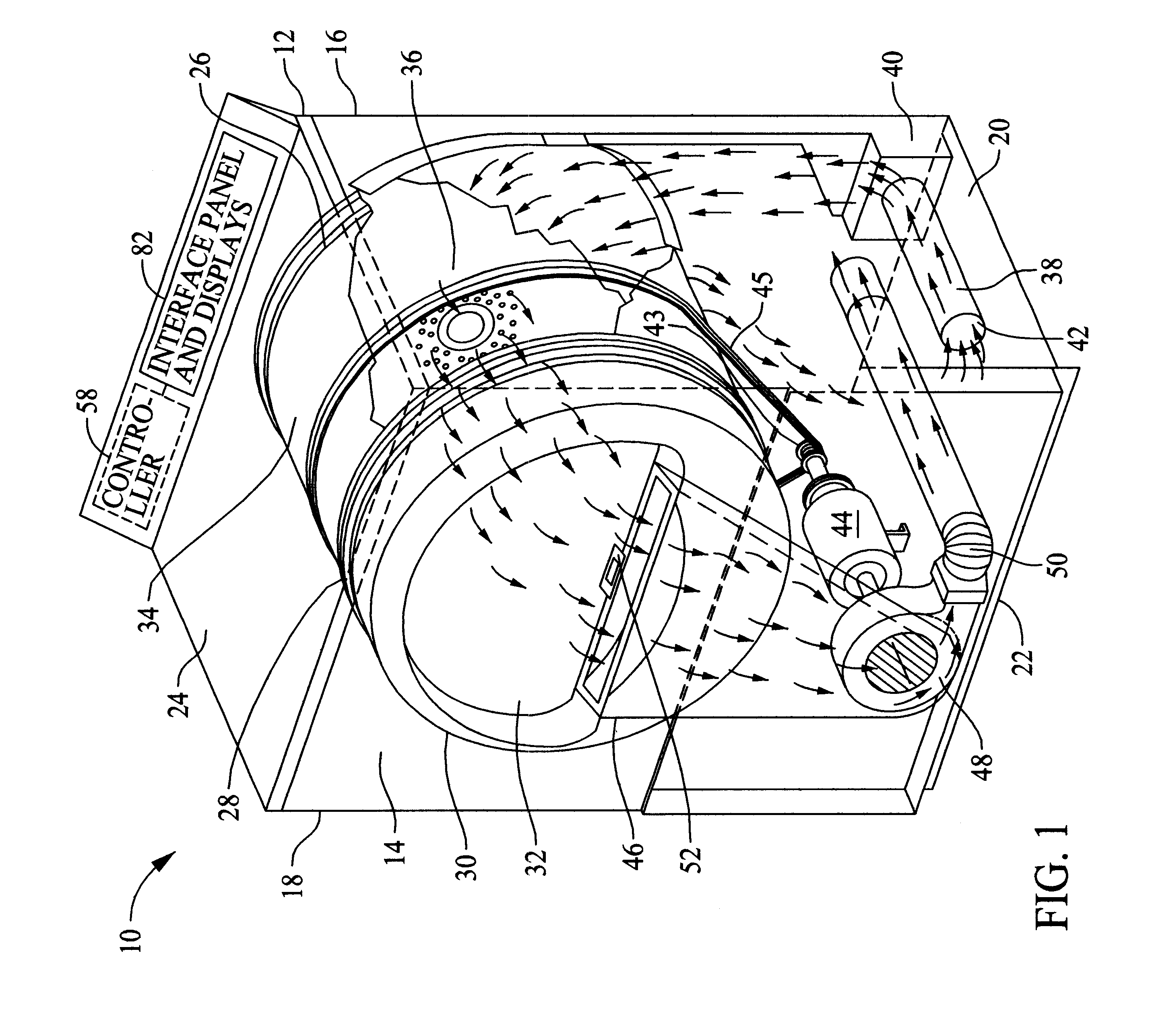
FIG. 1 shows a perspective view of an exemplary clothes dryer 10 that may benefit from the present invention. The clothes dryer includes a cabinet or a main housing 12 having a front panel 14, a rear panel 16, a pair of side panels 18 and 20 spaced apart from each other by the front and rear panels, a bottom panel 22, and a top cover 24. Within the housing 12 is a drum or container 26 mounted for rotation around a substantially horizontal axis. A motor 44 rotates the drum 26 about the horizontal axis through, for example, a pulley 43 and a belt 45. The drum 26 is generally cylindrical in shape, having an imperforate outer cylindrical wall 28 and a front flange or wall 30 defining an opening 32 to the drum. Clothing articles and other fabrics are loaded into the drum 26 through the opening 32. A plurality of tumbling ribs (not shown) are provided within the drum 26 to lift the articles and then allow them to tumble back to the bottom of the drum as the drum rotates. The drum 26 inclu...


PUM


Abstract

System and method for controlling an appliance for drying clothing articles is provided. The appliance has a container for receiving the clothing articles. A motor is provided for rotating the container about an axis. A heater is provided for supplying heated air to the container during a dry cycle. A sensor is provided for providing a signal indicative of moisture content of the articles. Memory is provided memory for storing historical stop time data of respective dry cycles. A noise-reduction filter is coupled to receive the signal from the moisture sensor to provide selectable filtering to that signal. A timer provides a signal indicative of elapsed time upon start of the dry cycle. A module is responsive to the historical data in the memory for determining an initial estimate of the stop time of the dry cycle to be executed. A processor allows for estimating the stop time of the dry cycle as the cycle is being executed. The estimation of the stop time is based on a respective functional relationship of the noise-reduced sensor signal, and the timer signal, relative to one or more characteristics of the articles and one or more desired values of predetermined dry-cycle parameters selectable by a respective user of the dryer. The initial estimate of the stop time is superceded by the stop time estimated by the processor as the cycle is being executed.

Description

BACKGROUND OF THE INVENTIONThe present invention is generally related to an appliance for drying articles, and, more particularly, the present invention is related to a dryer using microprocessor-based control for automatically shutting off the dryer.It is known that the optimum drying time for clothes varies greatly as a function of the fabric type and size of the load. For example, it is generally desirable to dry at a relatively high temperature so as to minimize the drying time, but some fabric types are damaged by hot temperatures. Also, different types of fabrics have different water storage capacities and different water removal rates. Since the drying results provided by known dryer control techniques are believed to be somewhat unpredictable, there is a need for a clothes dryer that can statistically and probabilistically estimate the time when the articles will reach a desired moisture content or degree of dryness with a high degree of accuracy, regardless of the specific ...

Claims


Application Information

Patent Timeline
Patent Type & Authority Patents(United States)
IPC IPC(8): D06F58/28D06F34/08D06F58/38D06F58/46
CPCD06F58/28D06F2058/2854D06F2058/2838D06F58/38D06F2103/10D06F2105/58D06F58/46D06F2105/56D06F2101/00D06F2105/60D06F34/08D06F2103/38D06F2103/44D06F2105/52D06F2105/46D06F2105/28
Inventor WUNDERLIN, WILLIAM JOSEPHDION, MICHELCAMBON, ALEXANDER CARSWELLISMAIL, MAHMOUD FARIZHAMEED, ZUBAIREMERY, CATHY DIANE
Owner HAIER US APPLIANCE SOLUTIONS INC
Why Eureka
Try Eureka